System For Grouping Users To Share Time-Frequency Resources In A Wireless Communication System

a wireless communication system and user technology, applied in the field of wireless communication systems, can solve the problems of packets not being decoded correctly, sticky radio resources assigned to users being left unused, and the possibility of unused or underutilized radio resources, so as to improve overall system efficiency, reduce the delay for users with time-sensitive applications, and shorten the delay of queuing

Inactive Publication Date: 2008-03-06
FUTUREWEI TECH CO
View PDF13 Cites 19 Cited by
  • Summary
  • Abstract
  • Description
  • Claims
  • Application Information

AI Technical Summary

Benefits of technology

[0013]The present invention provides a system, comprising various methods and apparatus, that enhances overall system efficiency by providing the ability for multiple users to share a same radio resource—thereby reducing delay for users with time-sensitive applications. The system of the present invention provides shorter queuing delay, and better QoS, for users with time-sensitive applications; by giving those users with time-sensitive application preferential treatment over users without time-sensitive applications. The preferential treatment may be, but is not limited to, higher priority access to shared resources, and a greater choice of shared resources for starting transmission of a new H-ARQ packet. The system of the present invention minimizes signaling overhead for configuring and assigning shared resources.

Problems solved by technology

However, when utilizing sticky assignments, there always exists a possibility of unused or underutilized radio resources.
When this occurs, sticky radio resources assigned to this user are left unused as the user waits for the arrival of a next VoIP packet.
In contrast, if a received sub-packet is not for a particular user, the unscrambling operation performed at the receiver does not reverse the scrambling process performed at the transmitter, and the packet cannot be decoded correctly.
Corruption of the detection buffer (i.e., a severe impairment to detection performance) can happen if symbols intended for a user are mixed with symbols intended for another user.
This can result in excessive delays for time-sensitive applications, such as VoIP, and result in degradation of quality of service (QoS).

Method used


Image

  • System For Grouping Users To Share Time-Frequency Resources In A Wireless Communication System
  • System For Grouping Users To Share Time-Frequency Resources In A Wireless Communication System
  • System For Grouping Users To Share Time-Frequency Resources In A Wireless Communication System

Examples


first embodiment

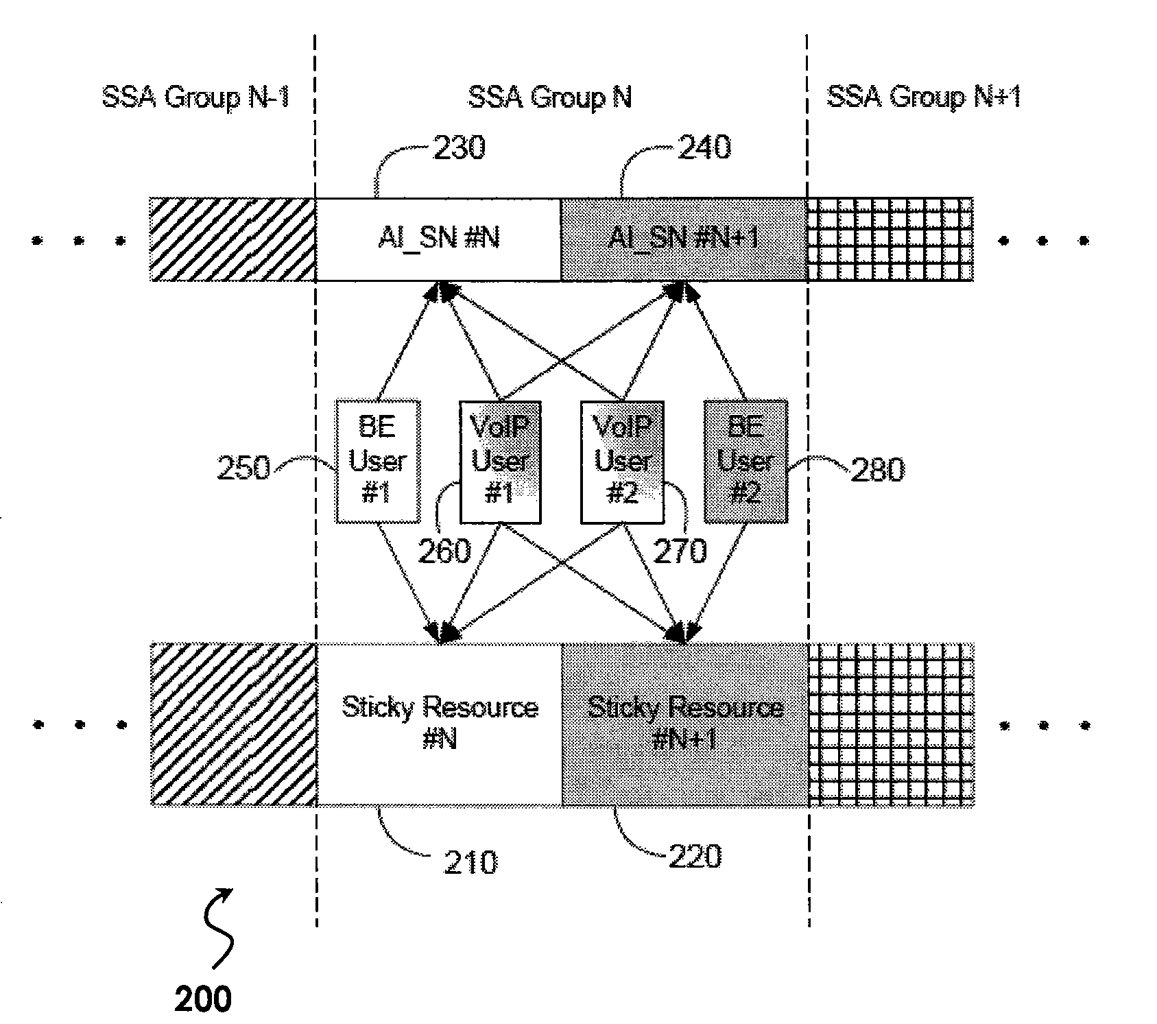
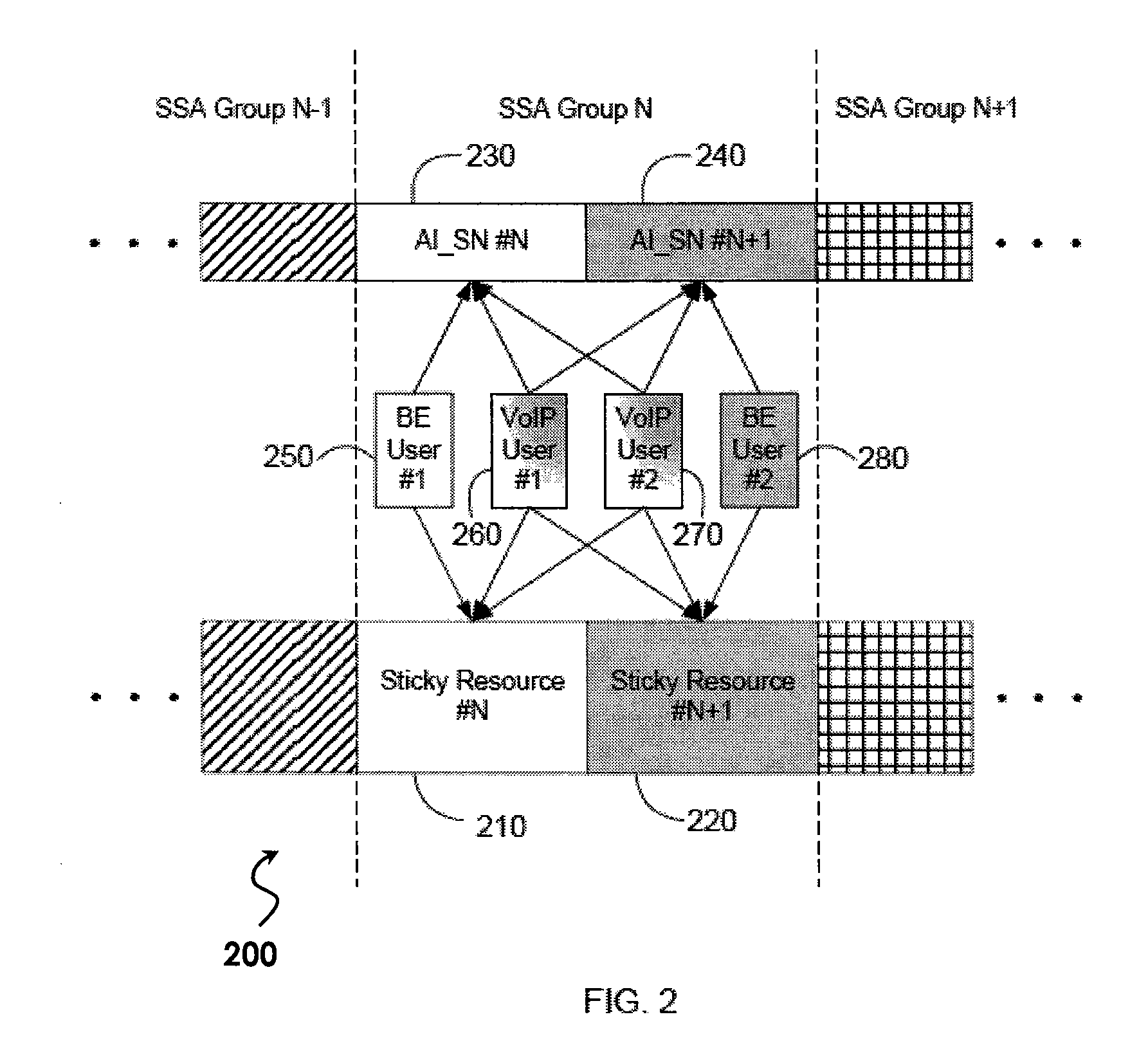
[0023]Referring now to FIG. 2, one embodiment of a resource-sharing scheme 200 according to the present invention is illustratively depicted. In FIG. 2, an SSA Group N comprises two shared sticky resources 210 and 220. In a first embodiment, each of these shared resources forms an independent channel to carry data traffic for different users. AI_SN indicators 230 and 240 indicate whether or not a new packet has started in the shared sticky resources 210 and 220, respectively. AI_SN indicators 230 or 240 may toggle between a first state and a second state when a new packet starts in each respective shared sticky resource. Otherwise, AI_SN indicator 230 or 240 may remain in its previous state. In the example depicted in FIG. 2, a BE user 250 and two VoIP users 260 and 270 share first sticky resource 210, while the same two VoIP users 260 and 270 and a second BE user 280 share second sticky resource 220.

[0024]A transmitter at an associated base station scrambles an encoded data sub-pac...

embodiment 300

[0030]In an alternative embodiment, each of the shared sticky resources within an SSA group may form independent channels, or pipes, to carry traffic for different users. One or more shared sticky resources within a group may alternatively form a combined channel, or pipe, to carry traffic for at least one user based on: channel and traffic conditions; the user type; the availability of each shared resource; and which shared resources are assigned to the scheduled user if not all shared resources within the SSA group are assigned to the scheduled user. For example, users whose traffic may be carried by the combined pipe may be limited to the non-VoIP users, as the data rate for a VoIP application is relatively constant. In this case, those users whose traffic can be carried by the combined pipe need to perform blind decoding, in view of the possibility that both the individually assigned shared pipe and the combined assigned shared pipe may carry the traffic for this user. FIG. 3 pr...

embodiment 200

[0032]Referring back to embodiment 200 of FIG. 2, users 250, 260, 270, and 280 are assigned to respective shared sticky resources with a sticky assignment. In addition, users without time-sensitive applications may be assigned to any of the shared resources, or combination of any of the shared resources, within an SSA group on a temporary basis (i.e., a non-sticky assignment); as long as those shared resources are available. Users assigned with non-sticky assignment to a shared resource do not need to perform blind decoding, or monitor the AI_SN indicator.

[0033]Therefore, sharing operation is transparent to a non-sticky user. Also, when the base station starts transmission of a new packet for a non-sticky user, assigning a non-sticky user to the shared sticky resources is also transparent to sticky users 250, 260, 270, and 280; as far as decoding is concerned. In order to decode their own packet, sticky users 250, 260, 270, and 280 each flush their respective detection buffer only w...


PUM


Abstract

A system of methods and constructs that enable multiple users to simultaneously share transmission (i.e., radio) resources, while reducing delay for users with delay-sensitive applications, is disclosed. The system provides for: forming one or more than one shared persistent (or “sticky”) assignment (SSA) group in a sector; allocating more than one shared sticky resource in at least one SSA group; and dividing users into at least a first class of users and a second class of users. The first class of users is given a higher priority to access the shared resources than the second class of users when the shared resources become available for a new packet. The first class of users is also given more choices of shared resources when starting transmission of a new packet.

Description

PRIORITY CLAIM[0001]This application claims the priority benefit of U.S. Provisional Application Ser. No. 60 / 824,283, filed on Aug. 31, 2006, entitled “METHOD AND APPARATUS FOR SHARING RADIO RESOURCES IN WIRELESS COMMUNICATION SYSTEM”, by Yunsong Yang, Anthony C. K. Soong and Jianmin LuREFERENCE TO RELATED APPLICATION FOR PATENT[0002]This application related to co-pending U.S. patent application Ser. No. 11 / 734,498, entitled METHOD AND APPARATUS FOR SHARING RADIO RESOURCES IN AN OFDMA-BASED COMMUNICATION SYSTEM, filed Apr. 12, 2007; which is assigned to the assignee hereof, and expressly incorporated by reference herein.TECHNICAL FIELD OF THE INVENTION[0003]The present invention relates generally to wireless communication systems and, more particularly, to a system for sharing of radio resources among a plurality of mobile stations while reducing latency for users with time-sensitive applications.BACKGROUND OF THE INVENTION[0004]In a wireless communication system, radio resources th...

Claims


Application Information

Patent Timeline
Patent Type & Authority Applications(United States)
IPC IPC(8): H04Q7/00H04W4/06H04W72/04
CPCH04W72/10H04W72/56
Inventor SOONG, ANTHONY C.K.YANG, YUNSONGLU, JIANMIN
Owner FUTUREWEI TECH CO
Why Eureka
Try Eureka