Loudspeaker
- Summary
- Abstract
- Description
- Claims
- Application Information
AI Technical Summary
Benefits of technology
Problems solved by technology
Method used
Image

Examples
first exemplary embodiment
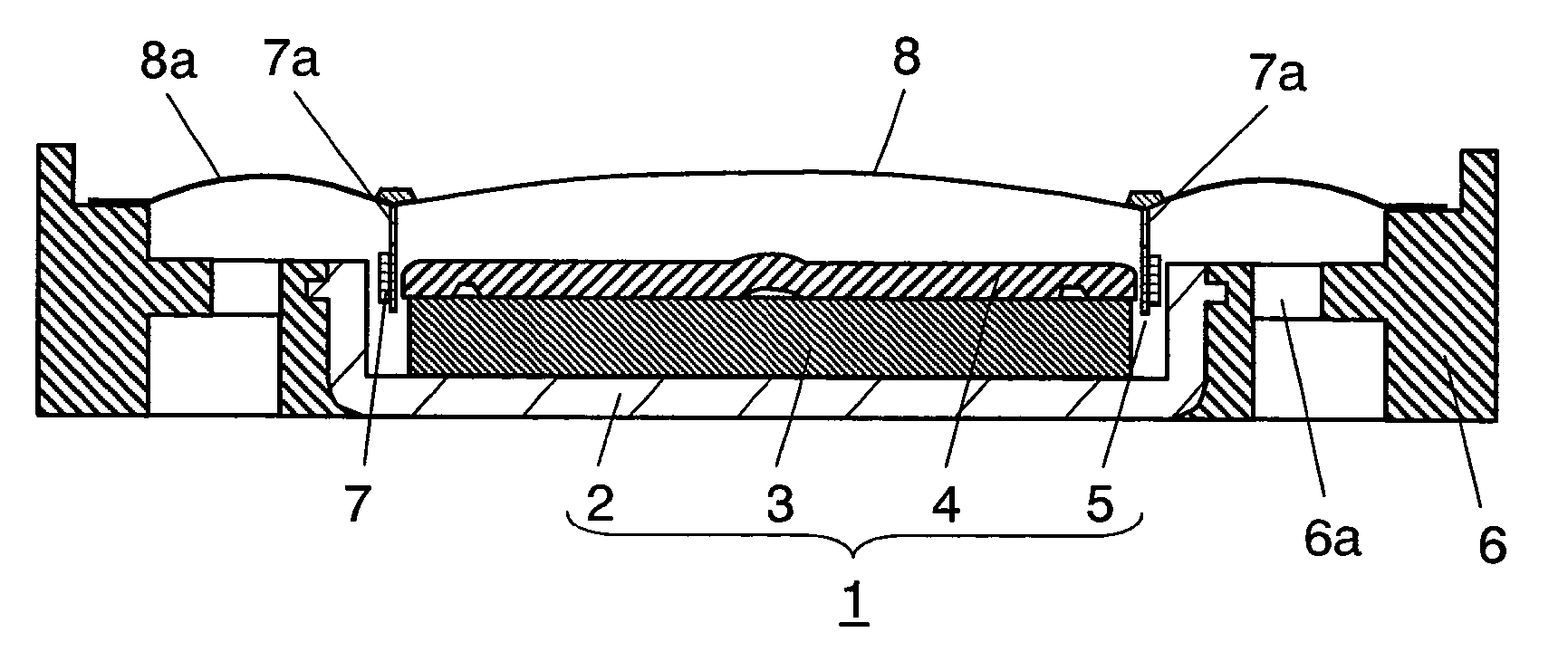
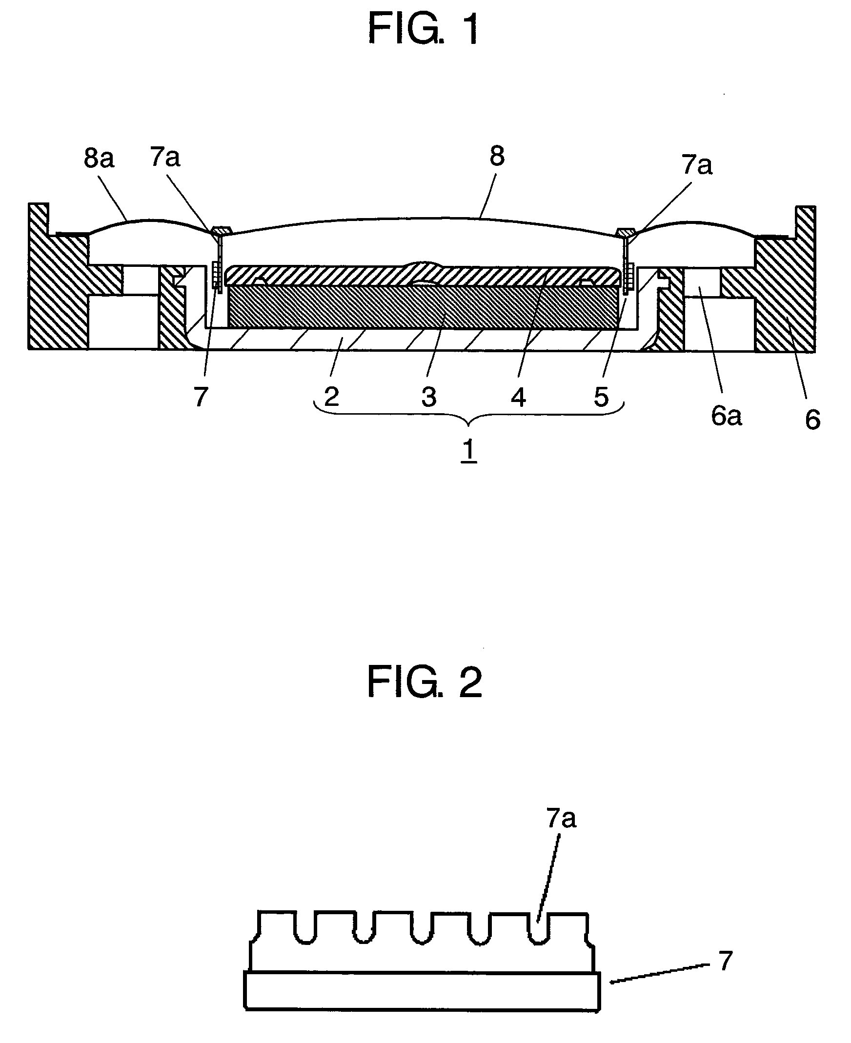
[0046] A first embodiment is described with reference to FIGS. 1 through 3.
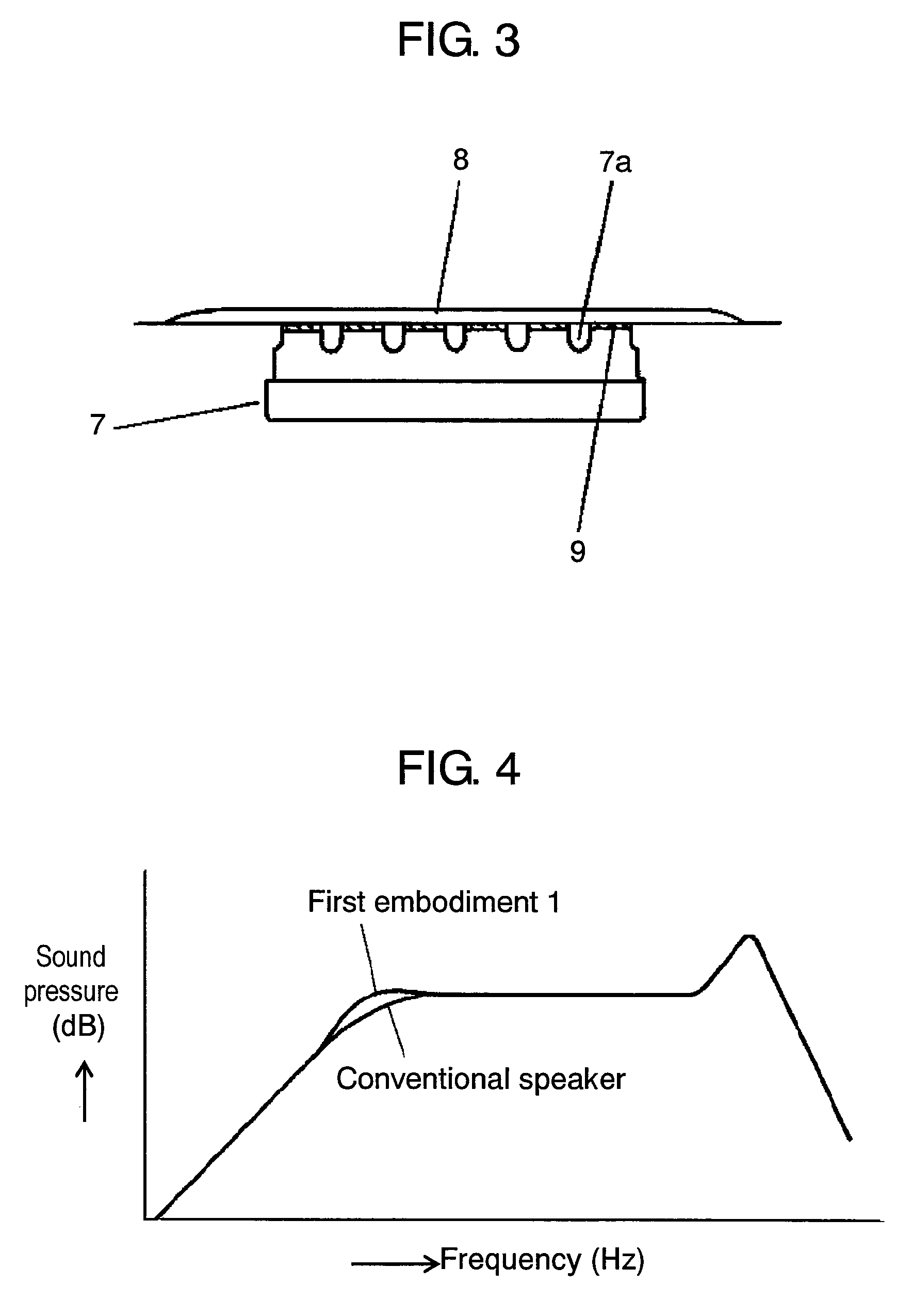
[0047] Magnetic circuit 1 is provided as an integration of disc-shape magnet 3 and plate 4 stacked in the inside of yoke 2 having a shallow canister shape. This provides magnetic gap 5 in a circular form. Frame 6 made of a resin material holds magnetic circuit 1 at its center. Frame 6 is provided with ventilation opening 6a. Voice coil 7 is disposed within magnetic gap 5 of magnetic circuit 1 in a free-moving manner. A bobbin forming voice coil 7 is provided with a plurality of cuts 7a at its upper end. Diaphragm 8 is coupled with voice coil 7, and fixed to frame 6 at its outer periphery. Edge portion 8a is provided integrally at a peripheral part of diaphragm 8. Edge portion 8a is fixed to frame 6 at its outer periphery. Voice coil 7 is connected with diaphragm 8 using adhesive agent 9. As shown in FIG. 3, they are connected together so that cut 7a formed at the upper end of the bobbin of voice coil 7 is no...
second exemplary embodiment
[0049] A pass-through structure of a loudspeaker in the present embodiment for connecting an air space formed between the reverse surface of a diaphragm and the inner side of voice coil to the outside is different from that of the first embodiment. The rest portions of the loudspeaker remain the same as those of the first embodiment, so that the identical portions are indicated by denoting with the same symbols and detailed descriptions thereof are eliminated. In the following, description is made on the portions different from those of the first embodiment.
[0050] The second embodiment is described hereinafter with reference to FIGS. 5 through 6B. Yoke 10 of a shallow canister form is provided with a plurality of through holes 10a at a periphery of its bottom. Magnetic circuit 12 having circular magnetic gap 11 is provided using the above-described yoke.
[0051] In a loudspeaker structured in accordance with the present embodiment, an air space formed between the reverse surface of ...
third exemplary embodiment
[0053] A pass-through structure of a loudspeaker in the present embodiment for connecting an air space formed between the reverse surface of a diaphragm and the inner side of voice coil to the outside is different from that of the first embodiment. The rest portions of the loudspeaker remain the same as those of the first embodiment, so that the identical portions are indicated by denoting with the same symbols and detailed descriptions thereof are eliminated. In the following, description is made on the portions different from those of the first embodiment.
[0054] The third embodiment is described hereinafter with reference to FIGS. 8 through 9B. Yoke 14 of a shallow canister form is provided with a plurality of cuts 14a at its side wall. Magnetic circuit 16 having circular magnetic gap 15 is provided using the above-described yoke.
[0055] In a loudspeaker structured in accordance with the present embodiment, an air space formed between the reverse surface of diaphragm 8 and the in...
PUM
 Abstract
Description
Claims
Application Information
 - Generate Ideas
- Intellectual Property
- Life Sciences
- Materials
- Tech Scout
- Unparalleled Data Quality
- Higher Quality Content
- 60% Fewer Hallucinations
Browse by: Latest US Patents, China's latest patents, Technical Efficacy Thesaurus, Application Domain, Technology Topic, Popular Technical Reports.
© 2025 PatSnap. All rights reserved.Legal|Privacy policy|Modern Slavery Act Transparency Statement|Sitemap|About US| Contact US: help@patsnap.com