Mold clamping device of injection molding machine

Inactive Publication Date: 2008-03-06
FANUC LTD
View PDF10 Cites 6 Cited by
  • Summary
  • Abstract
  • Description
  • Claims
  • Application Information

AI Technical Summary

Benefits of technology

[0015]According to the injection molding machine clamping device having the construction described above, simply by adding to a conventional toggle

Problems solved by technology

At the same time, because a large clamping force is required of the clamping device the force transmitted by the belt is also large, and therefore the belt sometimes breaks.
Moreover, with the method of detecting the rotations of the driven-side pulley taught by JP2003-74649A, there is no guarantee that, through malfunction of the mechanism part, the crosshead of

Method used


Image

  • Mold clamping device of injection molding machine
  • Mold clamping device of injection molding machine
  • Mold clamping device of injection molding machine

Examples


Example

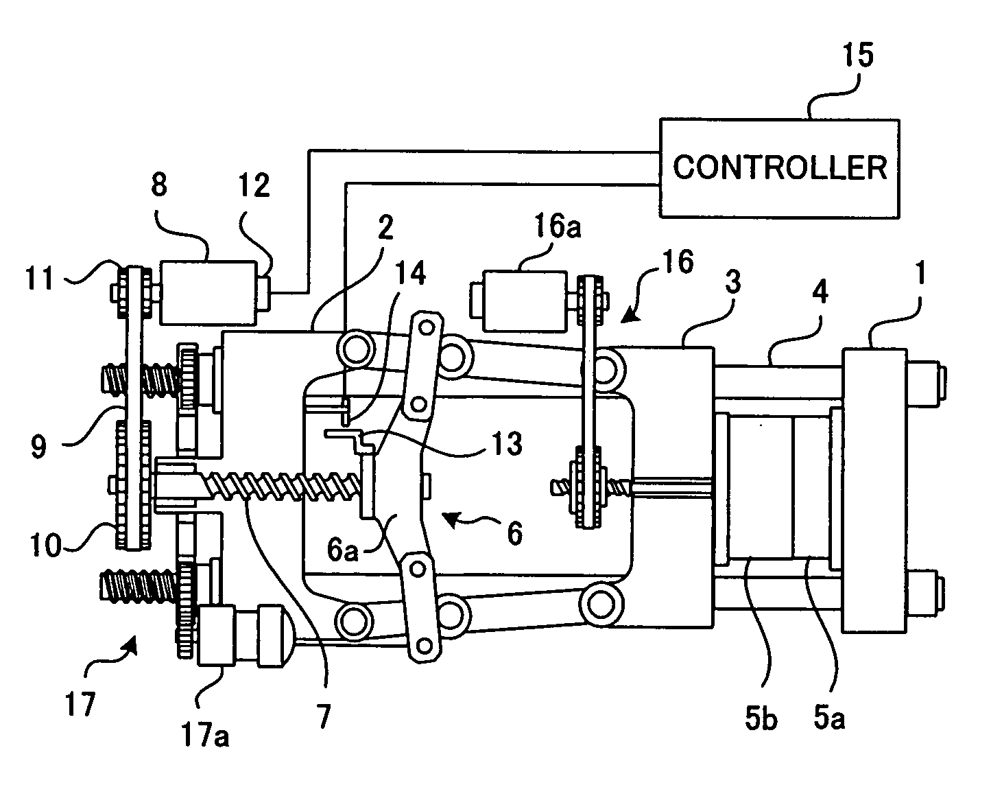
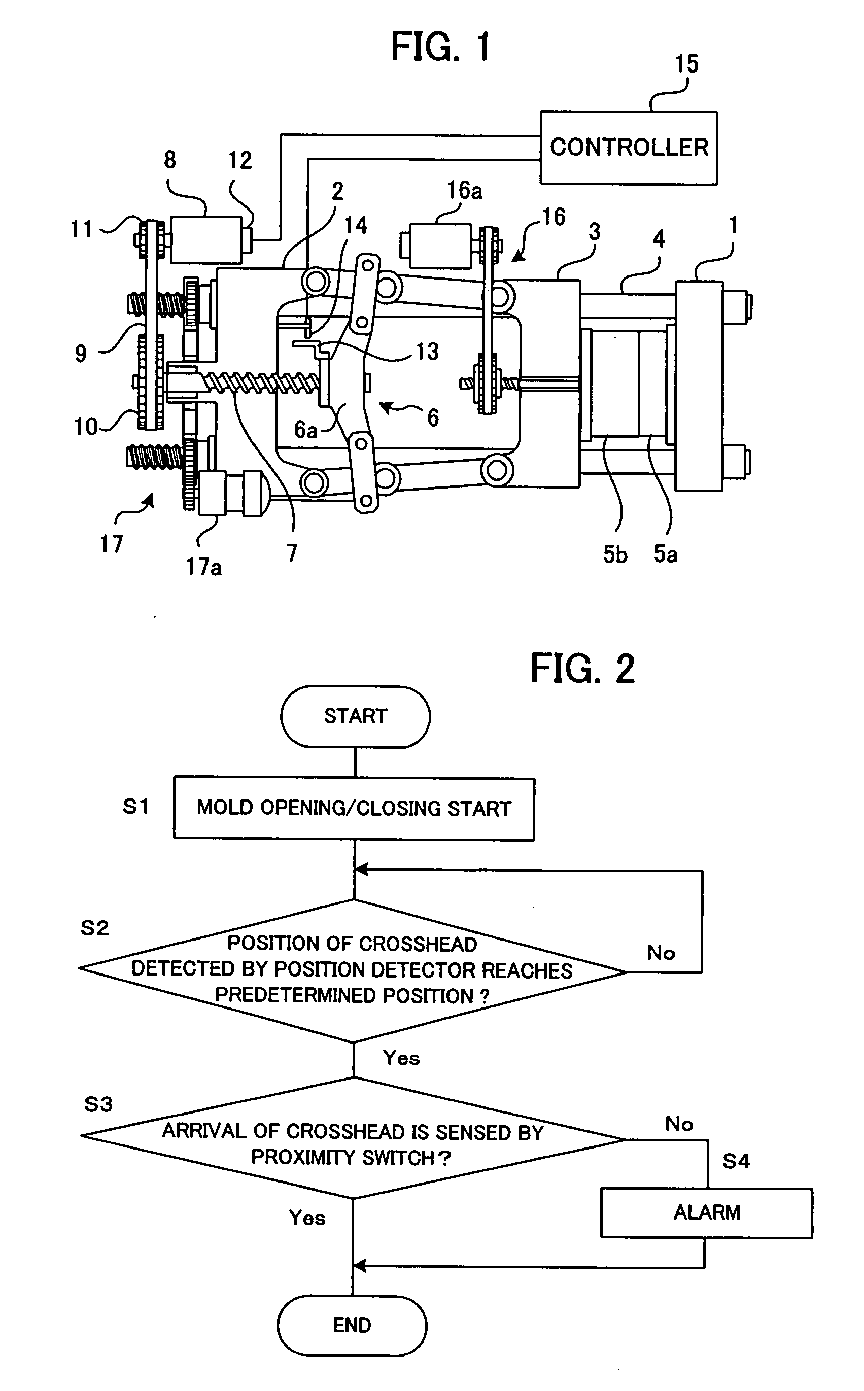
[0019]FIG. 1 is a schematic diagram of a clamping device according to an embodiment of the present invention. A stationary platen 1 and a rear platen 2 are coupled to each other by a plurality of tie bars 4. Between the stationary platen 1 and the rear platen 2 a movable platen 3 is disposed so as to be movable along the tie bars 4. In addition, a stationary mold half 5a is mounted on the stationary platen 1 and a movable mold 5 half b is mounted on the movable platen 3.

[0020]Between the rear platen 2 and the movable platen 3 a toggle mechanism 6 is disposed. A ball nut provided on a crosshead 6a of the toggle mechanism 6 engages a ball screw 7 mounted on the rear platen 2 so as to be rotatable but unmovable in an axial direction. A belt 9 is suspended between a pulley 10 provided on the ball screw 7 and a pulley 11 provided on an output shaft of a clamping servomotor 8 used for clamping. The ball screw 7 is driven by the drive of the clamping servomotor 8 via the pulley 11, the bel...


PUM

PropertyMeasurementUnit
Distanceaaaaaaaaaa

Abstract

In a toggle-type clamping device that drives by belt driving by a motor, to detect securely a break in a belt using a simple and inexpensive construction. A dog is mounted on a crosshead of a toggle mechanism, a proximity switch is mounted on a rear platen, and arrival of the crosshead at a predetermined position is detected. A position detector is mounted on a motor that drives the toggle mechanism via a belt and a ball screw. When arrival of the crosshead at the predetermined position (a mold touch position or a position at which the mold is open a predetermined distance from the mold touch position) is detected by the position detector, if the dog is not detected by the proximity switch, the clamping device outputs an alarm as an indication that an abnormality such as a break in the belt has occurred. Simply by adding to a conventional toggle-type clamping device a simple and inexpensive detection unit such as the proximity switch, the dog, and the like, abnormalities such as belt breakage and the like can be securely detected.

Description

BACKGROUND OF THE INVENTION[0001]1. Field of the Invention[0002]The present invention relates to a clamping device of an injection molding machine, and more particularly to a mold clamping device for clamping a mold by driving a toggle mechanism by a motor through a belt.[0003]2. Description of Related Art[0004]In injection molding machines, when driving a toggle-type clamping mechanism with a motor, a method that transmits torque of the motor through a belt to the toggle mechanism of a clamping device to drive the clamping device is commonly employed. In addition, a method that detects a position of a movable-side mold driven by the clamping device by a rotation position of the motor that drives the clamping device is also common.[0005]At the same time, because a large clamping force is required of the clamping device the force transmitted by the belt is also large, and therefore the belt sometimes breaks. A variety of methods have been proposed for detecting such belt breaks and p...

Claims


Application Information

Patent Timeline
IPC IPC(8): B29C45/80
CPCB29C45/661B29C45/768B29C45/80B29C2945/76923B29C2945/76083B29C2945/76093B29C2945/7623B29C45/84
Inventor NISHIMURA, KOICHIHASHIMOTO, NOBUAKI
Owner FANUC LTD
Why Eureka
Try Eureka