Zirconium Oxide-Based Dental Implant And Method For Producing Said Dental Implant

a zirconium oxide and dental implant technology, applied in dental implants, dental prosthetics, applications, etc., can solve the problem of hardly possible optimal fitting, and achieve the effect of convenient insertion

Active Publication Date: 2008-03-06
ZV3 - ZIRCON VISION
View PDF5 Cites 31 Cited by
  • Summary
  • Abstract
  • Description
  • Claims
  • Application Information

AI Technical Summary

Benefits of technology

[0005] It is an objective of the present invention to provide a dental implant which is an improvement over those cited above, and to provide a method of manufacturing said implant, in order to ensure optimal fitting combined with easy insertion and characteristics promoting a long service life.
[0007] The basis of the invention resides in the fact that only roughly ready-made green compacts (anchoring part and abutment) must be stored, while the surface processing necessary for osteogenic fusion can be performed in the dental laboratory, according to the measurements obtained there (tomographic images). Because this processing is done on the green compact, the surface can be roughened to an optimal degree, which would be nearly impossible for a finally sintered product on account of its great hardness. As a result of this individual surface configuration, even bone defects can be compensated by osteogenesis in an optimal way.
[0008] Preferably the special sections on the surface of the green compact are roughened by means of sand blasting. This technique is very simple and produces a surface roughness that optimally promotes osteogenesis.
[0009] The anchoring part and the abutment in one preferred embodiment of the invention are constructed as a single piece. This not only achieves optimal durability, but furthermore also results in an implant that is aesthetically optimal.
[0010] The transition region between the anchoring part and the abutment is preferably finished according to the individual dimensions of the patient's bone, in particular by processing the green compact. As a result, the individual conditions can be particularly well accommodated.
[0011] In one embodiment of the invention the anchoring part comprises a surface designed to be driven into a cylindrical or conical bore in the bone, as well as a concentric bore to receive a pin for the purpose of holding, guiding and driving in the anchoring part. This makes it possible to insert the implant especially precisely, with no need to employ elaborate templates or adjustment devices. In the case of an integral construction of anchoring part and abutment, the bore preferably runs through the abutment into the anchoring part, enabling the implant to be inserted exactly.

Problems solved by technology

What is problematic here is the fact that implants “ready-made” in this way must be stored in many different variants by the dental technician or at the factory, so that after the appropriate measurements of the patient have been made, the best-fitting implant can be selected.
Even so, an optimal fitting is hardly possible.

Method used


Image

  • Zirconium Oxide-Based Dental Implant And Method For Producing Said Dental Implant
  • Zirconium Oxide-Based Dental Implant And Method For Producing Said Dental Implant
  • Zirconium Oxide-Based Dental Implant And Method For Producing Said Dental Implant

Examples


Embodiment Construction

[0030] In the following description, the same reference numerals are used for identical parts and parts with identical actions.

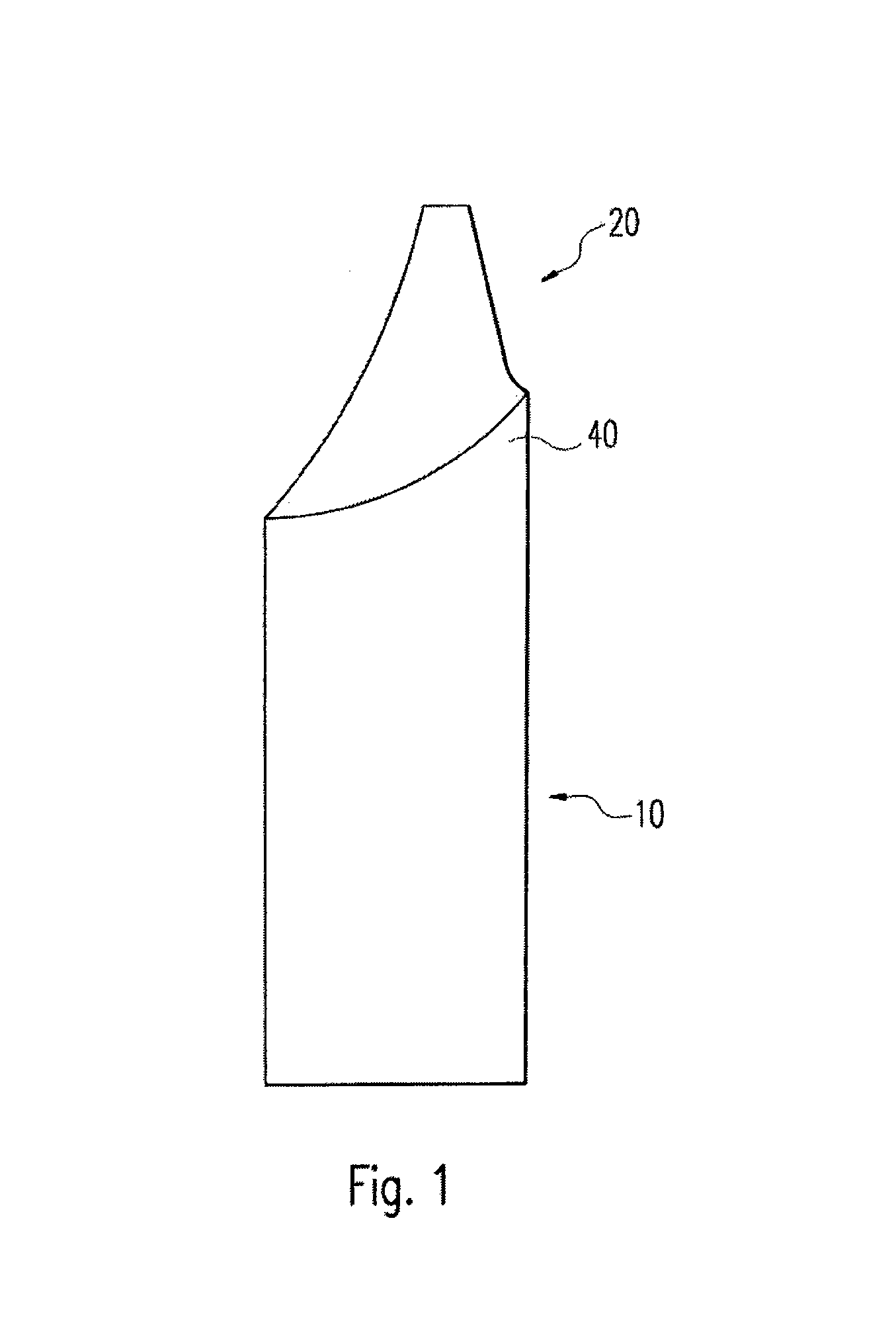
[0031] As shown in FIG. 1, the dental implant consists of an anchoring part 10 to anchor the dental implant in the bone, as well as an abutment 20 onto which the supraconstruction is set in a manner already known. The anchoring part comprises special sections 40, in particular in the region of the transition between anchoring part 10 and abutment 20, which have been produced on the green compact by sand blasting, in accordance with the patient's data.

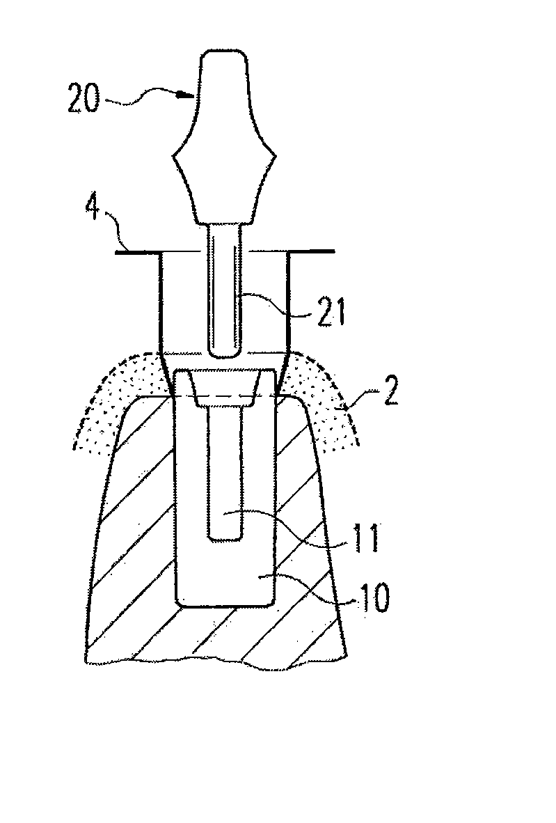
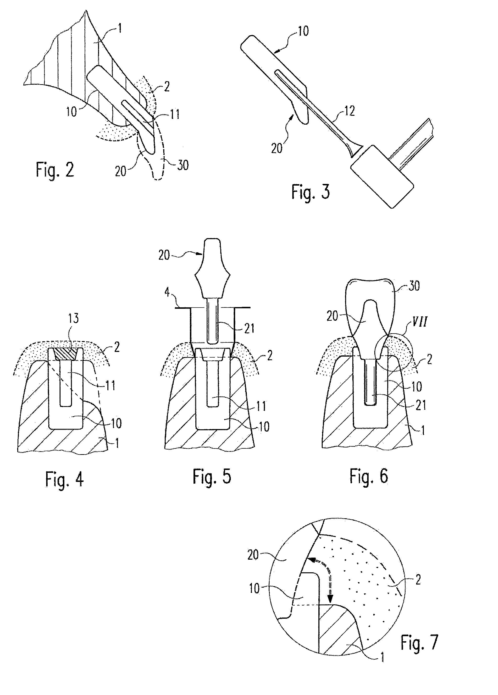
[0032]FIG. 2 shows how such a dental implant is inserted into a bone 1. For this purpose a cylindrical or (in the case of another appropriate configuration) slightly conical hole is bored into the bone and the dental implant is inserted. For this purpose a channel 11, in particular a cylindrical bore, has been formed within the dental implant so that a driving-in pin 12 can be inserted therein. This driving-in...


PUM

PropertyMeasurementUnit
dimensionsaaaaaaaaaa
shrinkageaaaaaaaaaa
hardnessaaaaaaaaaa

Abstract

A dental implant for a patient includes an anchoring part to anchor the dental implant in the bone and an abutment that is designed for fixation of a crown or similar supraconstruction and is or can be connected to the anchoring part. The anchoring part and the abutment are manufactured on a zirconium-oxide basis. The anchoring part and the abutment have special sections corresponding to the individual dimensions of the patient's bone and / or gums, said sections comprising a roughened surface designed to promote bone fusion. The special sections are produced on the green compact before the latter is finally sintered.

Description

CROSS-REFERENCE TO RELATED APPLICATIONS [0001] This application is a Section 371 of International Application No. PCT / EP2005 / 006010, filed Jun. 3, 2005, which was published in the German language on Dec. 22, 2005, under International Publication No. WO2005 / 120386 A1, the disclosure of which is incorporated herein by reference. BACKGROUND OF THE INVENTION [0002] The invention relates to a dental implant. [0003] For some time dental implants have been successfully employed. In many cases the material used for them is titanium, with which secure osteogenic fusion can be achieved. However, problems with their visual appearance can be avoided only by taking very elaborate measures. [0004] From the document DE 101 59 683 a dental implant of the kind cited above is known in which the transition between the implant, the abutment and the supraconstruction seated thereon does not present any such aesthetic problems, because the material used there is based on zirconium oxide. What is problema...

Claims


Application Information

Patent Timeline
Patent Type & Authority Applications(United States)
IPC IPC(8): A61C8/00A61C13/00
CPCA61C8/0006A61C8/0012A61C8/005A61C8/0054A61C13/0004A61C8/0075A61C8/0087A61C13/0003A61C8/0069
Inventor FEITH, JOHAN
Owner ZV3 - ZIRCON VISION
Why Eureka
Try Eureka