Low-cost interconnection system for solar energy modules and ancillary equipment

US20080057776A1Inactive Publication Date: 2008-03-06COOLEARTH SOLAR

Image

  • Low-cost interconnection system for solar energy modules and ancillary equipment
  • Low-cost interconnection system for solar energy modules and ancillary equipment
  • Low-cost interconnection system for solar energy modules and ancillary equipment

Examples


embodiment 302

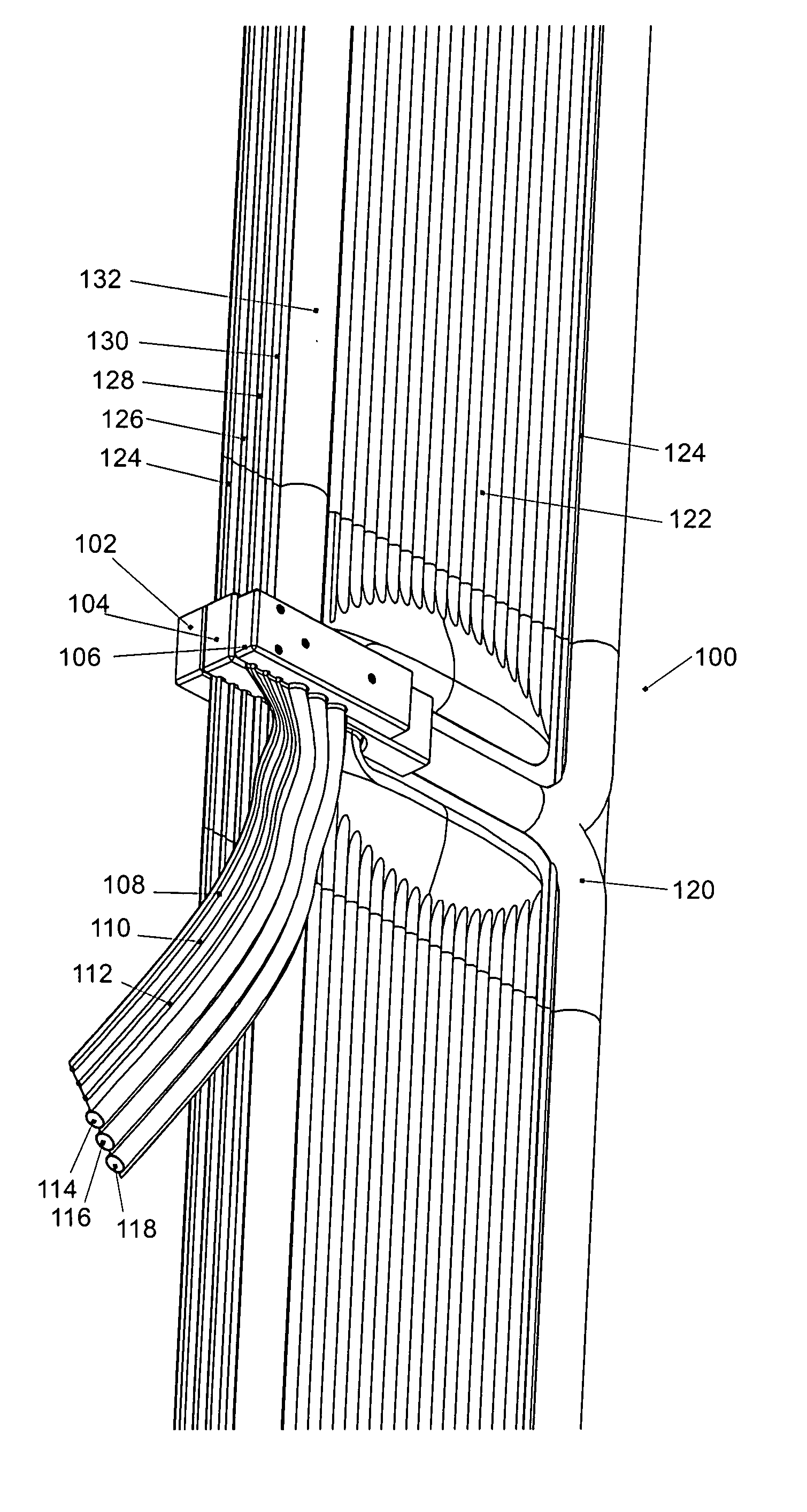
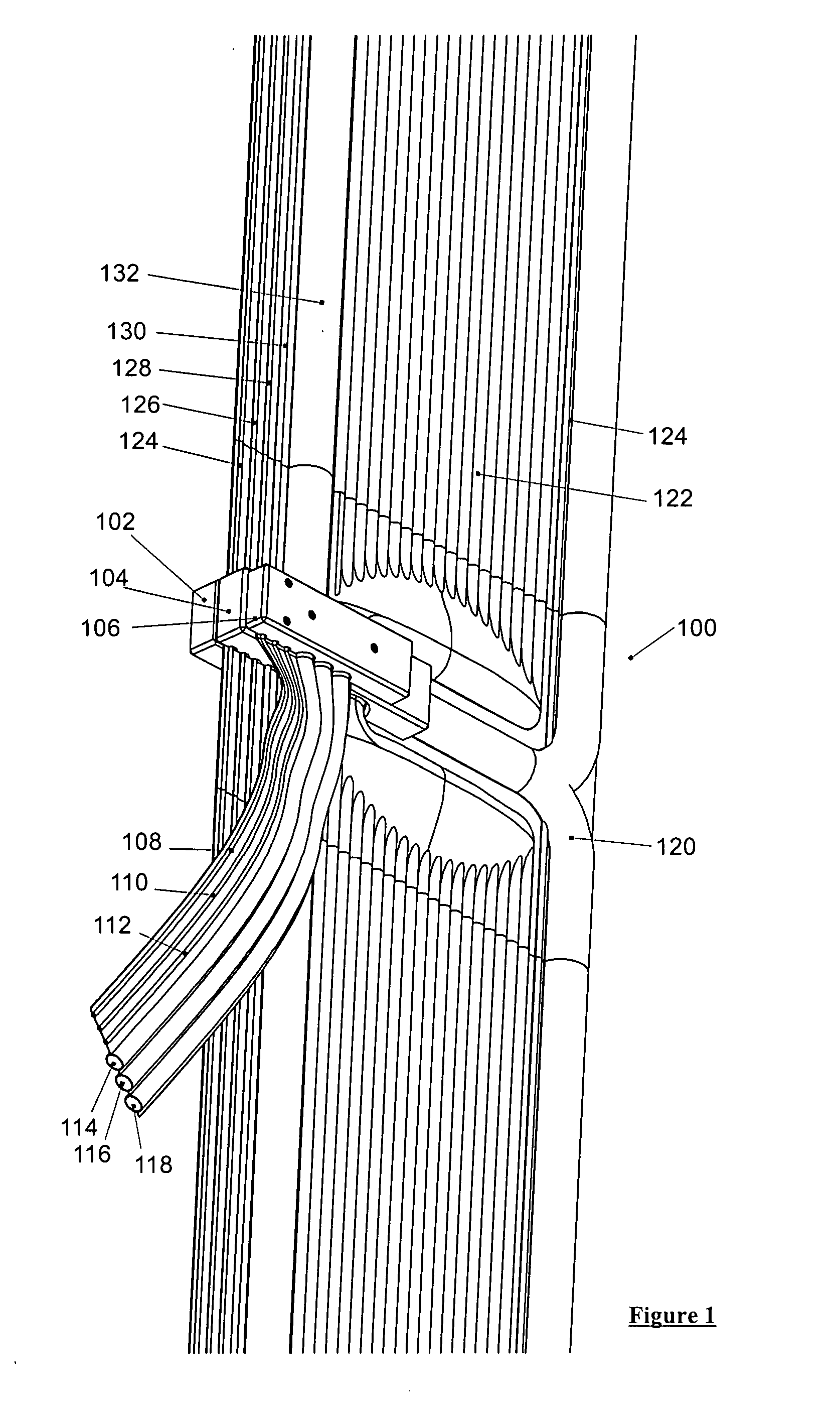
[0073] Under the combined influence of internal pressure, mechanical rigidity of the native film material or rigidity of inserted or incorporated materials, the regions indicated by white in FIG. 3AB form at least one conduit. In the embodiment 302 of the invention depicted in FIGS. 3A-BA, the conduit 318 contains a mechanical cable, e.g., a wire rope used to reinforce and support the multi-element cable; 320 and 322 hold electrical wires; 324 contains wires for networking and electronic sensing, signaling, and control; 326 forms a cavity for conveying cooling water; 328 are multiple cavities for conveying hot water from the concentrators; 330 holds a secondary mechanical cable; and 332 is a cavity for conveying inflation air. The cavities 328 are arranged to increase surface area to enhance heat transfer. The ordering size, presence and absence of these conduits or the presence of additional conduits of a different nature depends on the specifics of the application.

[0074] The order...

embodiment 500

[0102] FIGS. 5A-B shows an alternative embodiment 500 of the present invention in which the cable is manufactured to facilitate the use of more compact connectors at specific sites. Common manufacturing processes can support non-uniform channels, such as the plenum 510 that combines the parallel channels 508 and routes them to a single connector mate 512. An air conduit 506 is similarly routed to minimize the connector size. Because the location of a connector is prescribed by they features, a mechanical reinforcement lamination 504 can readily be incorporated at the time of manufacturing.

[0103] FIGS. 6A-B shows a connector installed or incorporated onto the cable in FIGS. 6A-B. This particular connector design is a “breakout” connector, in which the conduits of the cable are separately routed to a number of separate conventional conduits.

[0104]FIG. 7 shows an exploded view of such a breakout connector according to the present invention. In all cases, mechanical connections are sho...


PUM


Abstract

Embodiments in accordance with the present invention relate to inexpensive, manufacturable, robust, and easily installed interconnections for solar energy conversion systems. Particular embodiments in accordance with the present invention provide a convenient and low-cost means of interconnecting between one or more of solar energy modules and ancillary equipment electrical, hydraulic, pneumatic, and mechanical connections including one or more power-bearing electrical wires, cooling water conduits, compressed air conduits, electronic control and networking circuitry, conduits for chemical reactants and products, and mechanical linkages. Particular embodiments are further suitable for vibration control and damping of structures.

Description

CROSS-REFERENCES TO RELATED APPLICATIONS [0001] The instant nonprovisional patent application claims priority to U.S. Provisional Patent Application No. 60 / 839,855, filed Aug. 23, 2006 and incorporated by reference in its entirety herein for all purposes. The instant nonprovisional patent application is also related to the following provisional patent applications, each of which is incorporated by reference herein for all purposes: Appl. No. 60 / 839,841, filed Aug. 23, 2006; Appl. No. 60 / 840,156, filed Aug. 25, 2006; and Appl. No. 60 / 840,110, filed Aug. 25, 2006.BACKGROUND OF THE INVENTION [0002] Solar radiation is the most abundant energy source on earth. However, attempts to harness solar power at large scales has so far failed to be economically competitive with most fossil-fuel energy sources. One possible reason for this is that the solar flux is not intense enough for direct conversion at one solar flux to be cost effective. [0003] Solar concentrator technology seeks to address...

Claims


Application Information

Patent Timeline
06 Mar 2008
Publication
US20080057776A1
IPC
H01R4/00; F16L53/00; F16L55/02; F16L9/19
CPC
H01R13/005; F24J2/4647; F24S80/30
Inventors
CUMMINGS, ERIC BRYANT