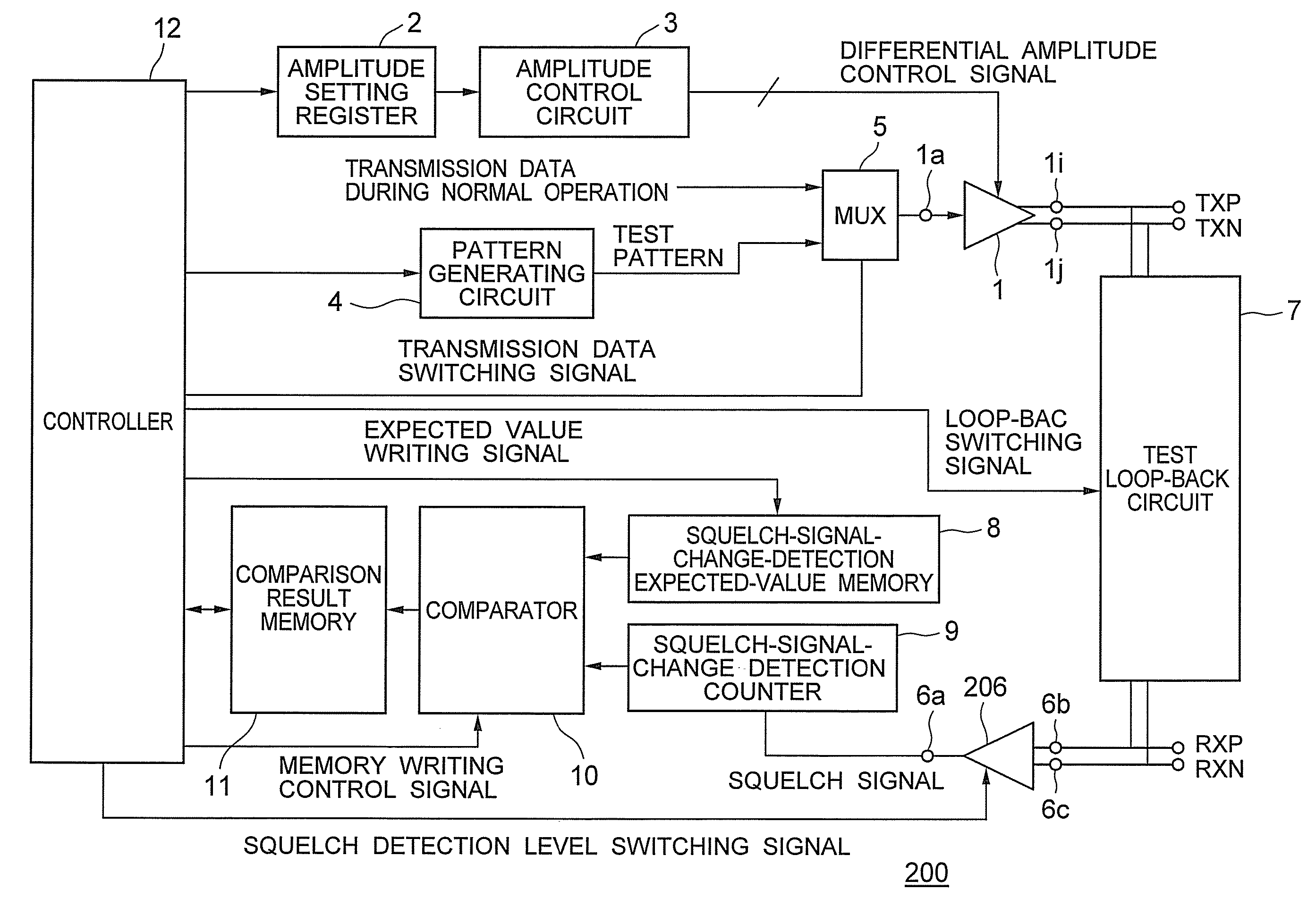
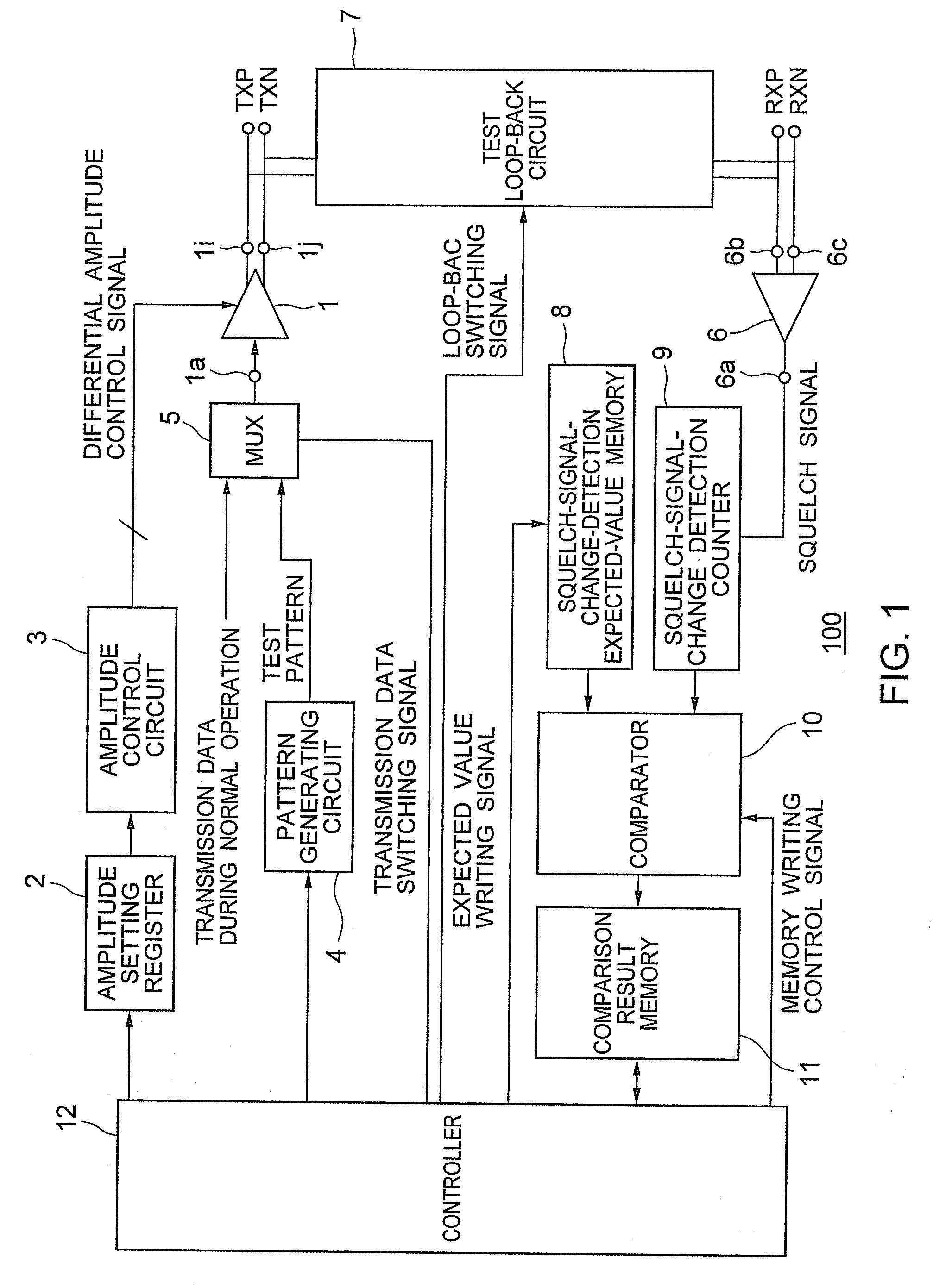
[0012] According one aspect of the present invention, there is provided: an automatic adjustment circuit for amplitude of differential signal comprising a differential signal transceiver that outputs differential signals according to a pattern of transmission data; an amplitude setting register in which plural setting values for setting amplitude of the differential signals outputted by the differential signal transceiver are stored; an amplitude control circuit that controls, on the basis of the setting value, the amplitude of the differential signals outputted by the differential signal transceiver; a pattern generating circuit that outputs a test pattern for discriminating an output amplitude level of the differential signals; a multiplexer that switches a test pattern outputted by the pattern generating circuit and a pattern of transmission data during a normal operation and outputs the patterns to the differential signal transceiver; a squelch detection receiver that receives the differential signals, compares the amplitude level of the differential signals and a first squelch detection level set as a reference, and outputs a squelch signal according to a result of the comparison; a test loop-back circuit that is capable of causing an output of the differential signal transceiver and an input of the squelch detection receiver to communicate with each other; a squelch-signal-change-detection expected-value memory that stores an expected value of a change in a squelch signal; a squelch-signal-change detection counter that detects a change in the squelch signal and counts the change; a comparator that compares the expected value stored in the squelch-signal-change-detection expected-value memory and a count value counted by the squelch-signal-change detection counter and outputs a difference value; a comparison result memory that stores the difference value; and a controller that controls at least the amplitude setting register, the pattern generating circuit, the test loop-back circuit, the multiplexer, and the comparison result memory, wherein the controller: causes the pattern generating circuit to output the test pattern, causes the multiplexer to output the test pattern by outputting a transmission data switching signal to the multiplexer, causes, according to the setting value stored in the amplitude setting register, the amplitude control circuit to change an output amplitude level of differential signals for test outputted by the differential signal transceiver, causes an output of the differential signal transceiver and an input of the squelch detection receiver to communicate with each other through the test loop-back circuit by outputting a loop-back switching signal to the test loop-back circuit, and transmits the differential signals for test from the output of the differential signal transceiver to the input of the squelch detection receiver, the squelch-signal-change detection counter counts a change in the squelch signal outputted from the squelch detection receiver according to input of the differential signals for test, the comparator compares, according to the output amplitude level of the differential signals for test, a count value of the count and the expected value stored in the squelch-signal-change-detection expected-value memory and outputs a difference value, the comparison result memory stores the difference value according to the output amplitude level of the differential signal for a test, and the controller extracts, out of the plural setting values stored in the amplitude setting register, the setting value corresponding to the output amplitude level of the differential signals for test, for which the difference value is zero, as a setting value used during the normal operation and specifies the setting value.
[0013] According another aspect of the present invention, there is provided a semiconductor device, comprising: an automatic adjustment circuit for amplitude of differential signal comprising a differential signal transceiver that outputs differential signals according to a pattern of transmission data; an amplitude setting register in which plural setting values for setting amplitude of the differential signals outputted by the differential signal transceiver are stored; an amplitude control circuit that controls, on the basis of the setting value, the amplitude of the differential signals outputted by the differential signal transceiver; a pattern generating circuit that outputs a test pattern for discriminating an output amplitude level of the differential signals; a multiplexer that switches a test pattern outputted by the pattern generating circuit and a pattern of transmission data during a normal operation and outputs the patterns to the differential signal transceiver; a squelch detection receiver that receives the differential signals, compares the amplitude level of the differential signals and a first squelch detection level set as a reference, and outputs a squelch signal according to a result of the comparison; a test loop-back circuit that is capable of causing an output of the differential signal transceiver and an input of the squelch detection receiver to communicate with each other; a squelch-signal-change-detection expected-value memory that stores an expected value of a change in a squelch signal; a squelch-signal-change detection counter that detects a change in the squelch signal and counts the change; a comparator that compares the expected value stored in the squelch-signal-change-detection expected-value memory and a count value counted by the squelch-signal-change detection counter and outputs a difference value; a comparison result memory that stores the difference value; and a controller that controls at least the amplitude setting register, the pattern generating circuit, the test loop-back circuit, the multiplexer, and the comparison result memory, wherein the amplitude setting resister includes a nonvolatile memory, the controller: causes the pattern generating circuit to output the test pattern, causes the multiplexer to output the test pattern by outputting a transmission data switching signal to the multiplexer, causes, according to the setting value stored in the amplitude setting register, the amplitude control circuit to change an output amplitude level of differential signals for test outputted by the differential signal transceiver, causes an output of the differential signal transceiver and an input of the squelch detection receiver to communicate with each other through the test loop-back circuit by outputting a loop-back switching signal to the test loop-back circuit, and transmits the differential signals for test from the output of the differential signal transceiver to the input of the squelch detection receiver, the squelch-signal-change detection counter counts a change in the squelch signal outputted from the squelch detection receiver according to input of the differential signals for test, the comparator compares, according to the output amplitude level of the differential signals for test, a count value of the count and the expected value stored in the squelch-signal-change-detection expected-value memory and outputs a difference value, the comparison result memory stores the difference value according to the output amplitude level of the differential signal for a test, and the controller extracts, out of the plural setting values stored in the amplitude setting register, the setting value corresponding to the output amplitude level of the differential signals for test, for which the difference value is zero, as a setting value used during the normal operation and specifies the setting value.
[0014] According further aspect of the present invention, there is provided a semiconductor device, comprising: an automatic adjustment circuit for amplitude of differential signal comprising a differential signal transceiver that outputs differential signals according to a pattern of transmission data; an amplitude setting register in which plural setting values for setting amplitude of the differential signals outputted by the differential signal transceiver are stored; an amplitude control circuit that controls, on the basis of the setting value, the amplitude of the differential signals outputted by the differential signal transceiver; a pattern generating circuit that outputs a test pattern for discriminating an output amplitude level of the differential signals; a multiplexer that switches a test pattern outputted by the pattern generating circuit and a pattern of transmission data during a normal operation and outputs the patterns to the differential signal transceiver; a squelch detection receiver that receives the differential signals, compares the amplitude level of the differential signals and a first squelch detection level set as a reference, and outputs a squelch signal according to a result of the comparison; a test loop-back circuit that is capable of causing an output of the differential signal transceiver and an input of the squelch detection receiver to communicate with each other; a squelch-signal-change-detection expected-value memory that stores an expected value of a change in a squelch signal; a squelch-signal-change detection counter that detects a change in the squelch signal and counts the change; a comparator that compares the expected value stored in the squelch-signal-change-detection expected-value memory and a count value counted by the squelch-signal-change detection counter and outputs a difference value; a comparison result memory that stores the difference value; and a controller that controls at least the amplitude setting register, the pattern generating circuit, the test loop-back circuit, the multiplexer, and the comparison result memory, wherein the amplitude setting resister includes a fuse element or a flash memory, the controller: causes the pattern generating circuit to output the test pattern, causes the multiplexer to output the test pattern by outputting a transmission data switching signal to the multiplexer, causes, according to the setting value stored in the amplitude setting register, the amplitude control circuit to change an output amplitude level of differential signals for test outputted by the differential signal transceiver, causes an output of the differential signal transceiver and an input of the squelch detection receiver to communicate with each other through the test loop-back circuit by outputting a loop-back switching signal to the test loop-back circuit, and transmits the differential signals for test from the output of the differential signal transceiver to the input of the squelch detection receiver, the squelch-signal-change detection counter counts a change in the squelch signal outputted from the squelch detection receiver according to input of the differential signals for test, the comparator compares, according to the output amplitude level of the differential signals for test, a count value of the count and the expected value stored in the squelch-signal-change-detection expected-value memory and outputs a difference value, the comparison result memory stores the difference value according to the output amplitude level of the differential signal for a test, and the controller extracts, out of the plural setting values stored in the amplitude setting register, the setting value corresponding to the output amplitude level of the differential signals for test, for which the difference value is zero, as a setting value used during the normal operation and specifies the setting value.


