Autotensioner

a technology of autotensioner and spindle, which is applied in the direction of gearing, bearing components, shafts and bearings, etc., can solve the problems of affecting the performance of the autotensioner

Inactive Publication Date: 2008-03-06
BANDO CHEM IND LTD
View PDF5 Cites 22 Cited by
  • Summary
  • Abstract
  • Description
  • Claims
  • Application Information

AI Technical Summary

Benefits of technology

[0017]In a fourth aspect of the present invention, the autotensioner is provided in an accessory drive system for driving accessories of a diesel engine for a midsize or large size vehicle. This provides an autotensioner optimal for applications requiring a long service life.

Problems solved by technology

This very small clearance makes it difficult for the autotensioner to cause percussive wear or fretting between the spindle and the bush even if large short quick vibrations are input to the autotensioner.

Method used


Image

  • Autotensioner
  • Autotensioner
  • Autotensioner

Examples


Embodiment Construction

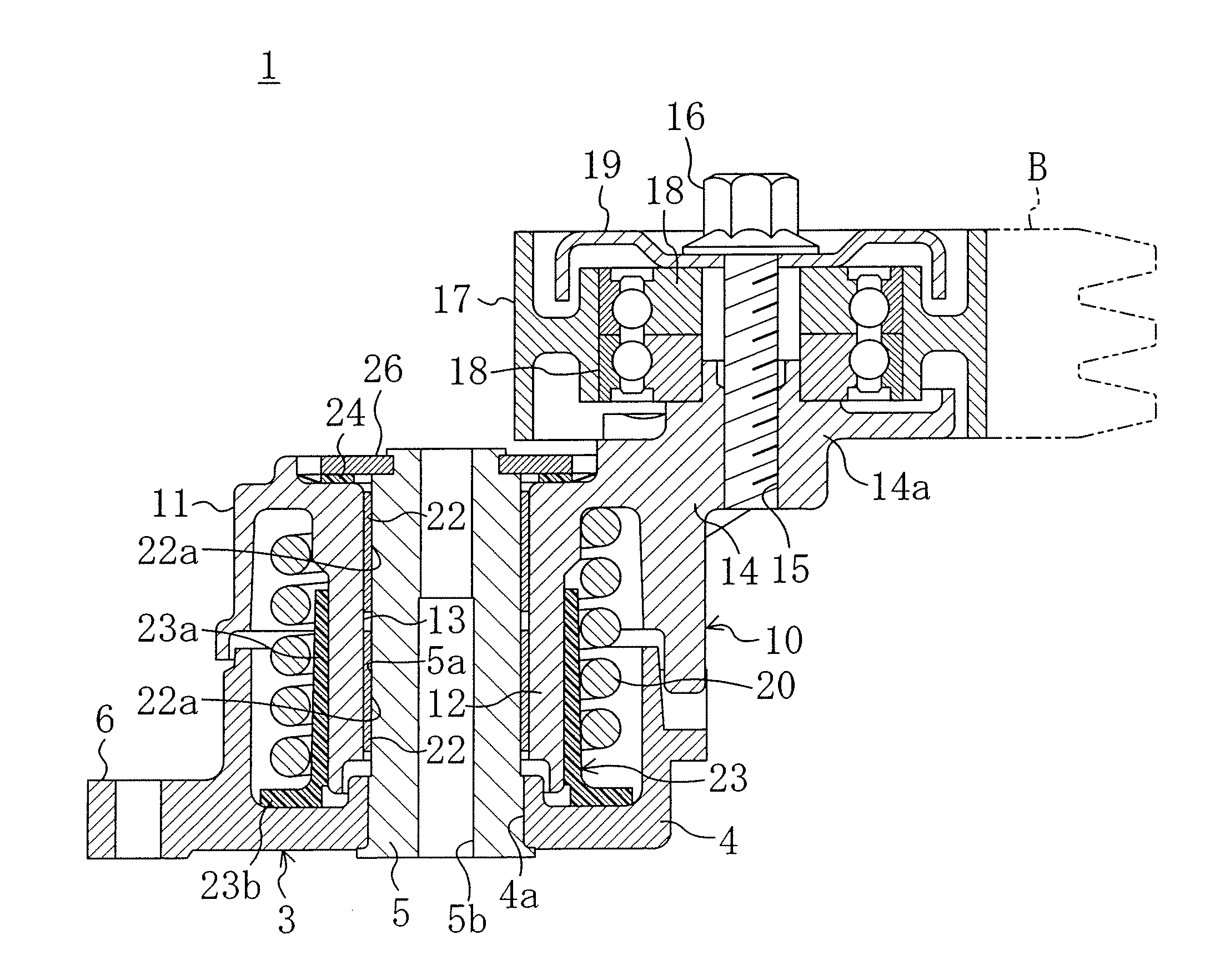
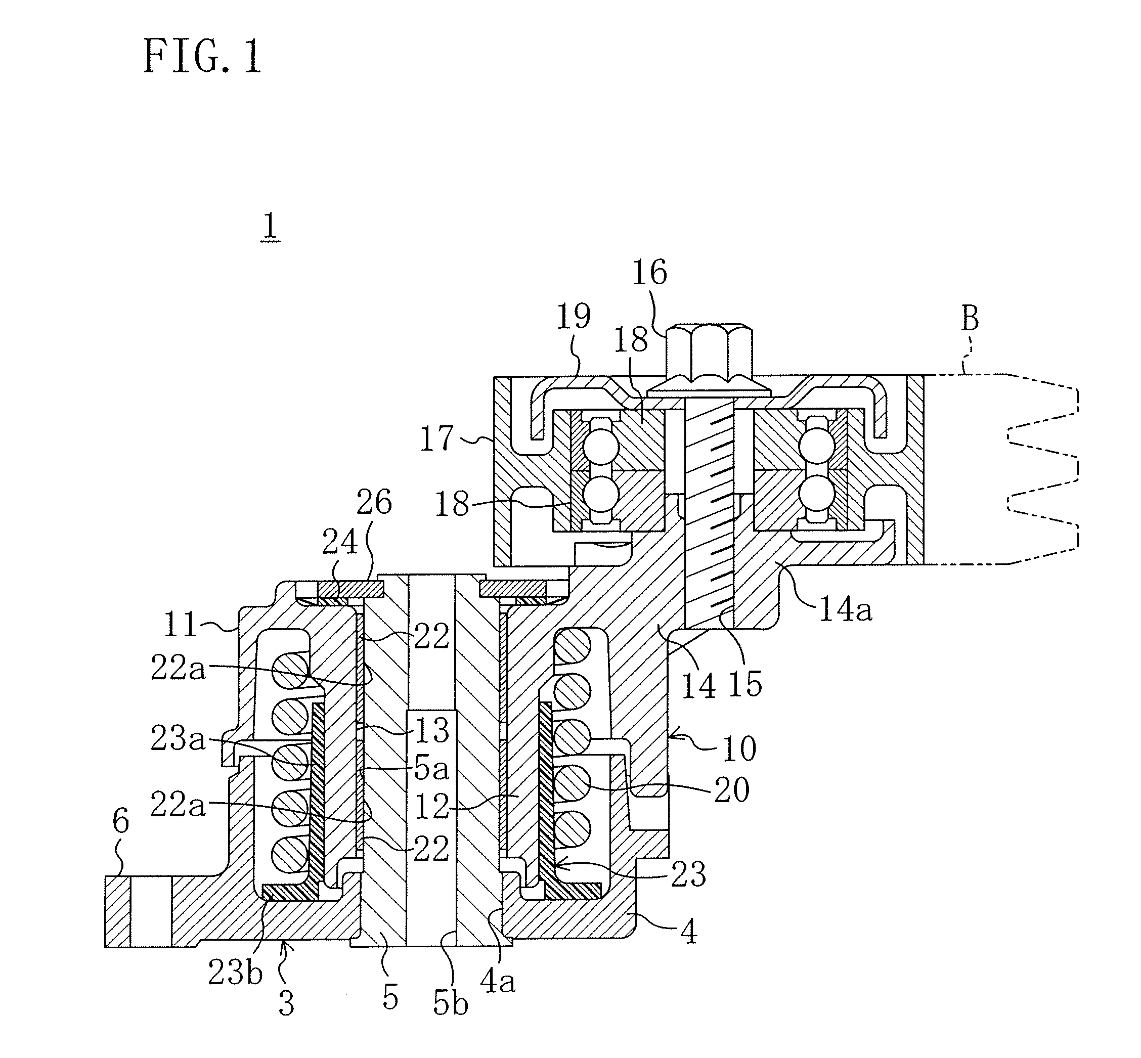
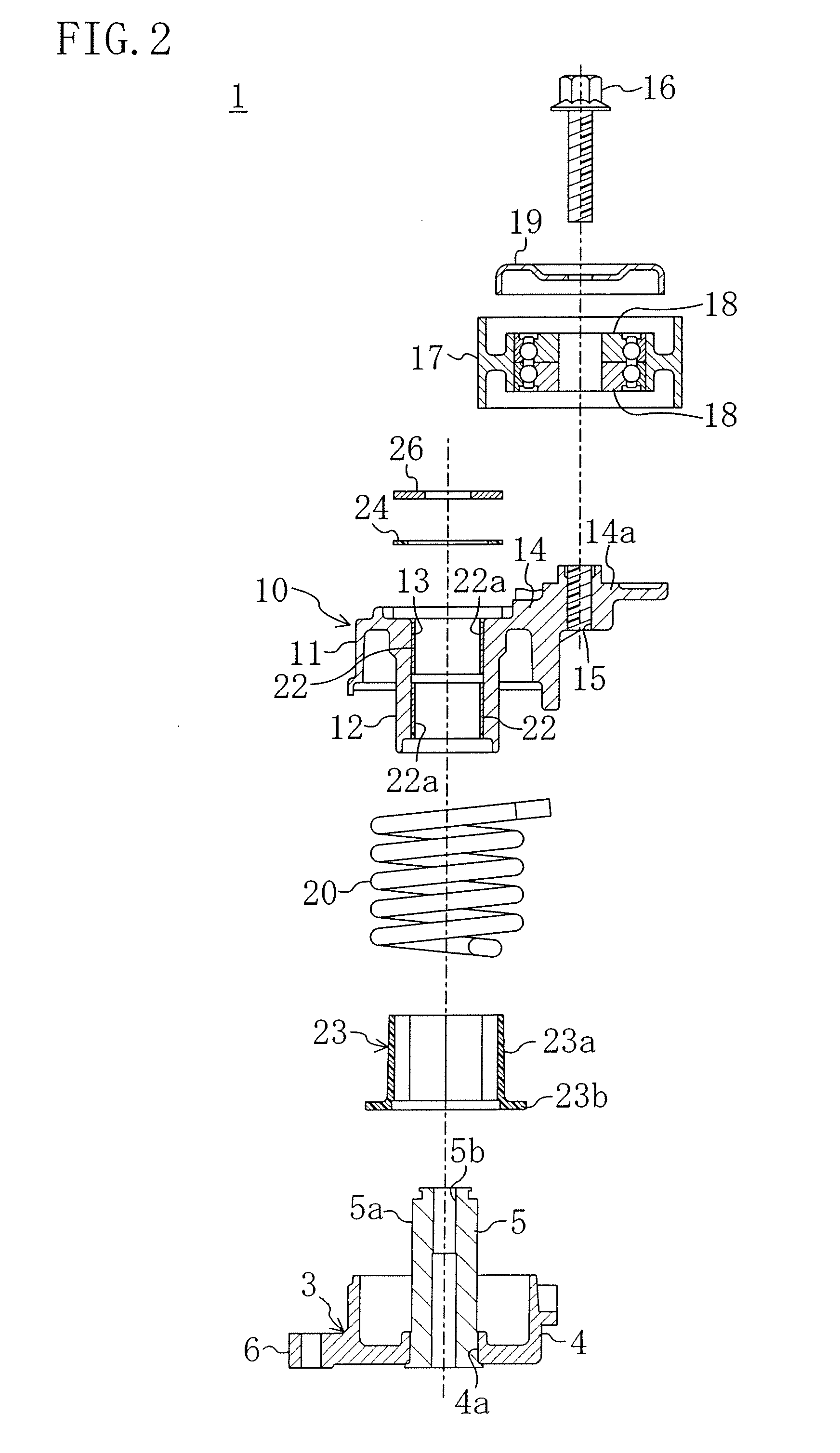
[0022]The best mode of the present invention will be described below in detail with reference to the drawings. The following description of the preferred embodiment is merely illustrative in nature and is not intended to limit the scope, applications and use of the invention.

[0023]In FIG. 1, reference numeral 1 denotes an autotensioner according to an embodiment of the present invention. The autotensioner 1 is used in a belt drive system, such as a diesel engine accessory drive system (not shown) mounted on a midsize or large size vehicle (of 10 or more deadweight ton), such as a truck.

[0024]The accessory drive system, although not shown, includes a crank pulley formed of a V-ribbed pulley carried on, for example, the crank shaft of a vehicle-mounted engine, a compressor pulley formed of a V-ribbed pulley carried on the rotational shaft of a compressor (accessory) for an air conditioner, a PS pump pulley formed of a V-ribbed pulley carried on the rotational shaft of a power steering...


PUM


Abstract

In an autotensioner of a type in which a boss of an oscillating member is pivotally fitted on a spindle of a stationary member through a bush including a metal part and a resin layer formed on the inner periphery of the metal part, the clearance in its initially assembled state between the outer periphery of the spindle and the inner periphery of the bush is 60 μm or less to make it difficult to cause fretting between the spindle and the bush even upon input of large short quick vibrations to the autotensioner and thereby extend the service life of the autotensioner. Furthermore, the spindle has a surface hardness of Hv 500 or more to prevent wear of the spindle itself from progressing even upon occurrence of fretting.

Description

CROSS-REFERENCE TO RELATED APPLICATION[0001]This application claims priority under 35 USC 119 to Japanese Patent Application No. 2006-231724 filed on Aug. 29, 2006, the entire contents of which are incorporated herein by reference.BACKGROUND OF THE INVENTION[0002](a) Field of the Invention[0003]This invention relates to autotensioners and particularly relates to the technique for preventing the shortening of their service life due to fretting.[0004](b) Description of the Related Art[0005]An autotensioner is conventionally known which is used, for example, in a belt accessory drive system for a vehicle engine, applies tension to a belt and damps the action of applying the tension, thereby preventing bouncing (fluttering) of the belt and providing stable torque transmission.[0006]Specifically, as disclosed in Published Japanese Patent Application No. H03-20146, such an autotensioner includes a stationary member fixedly mounted, for example, to an engine, a movable part, such as an arm...

Claims


Application Information

Patent Timeline
Patent Type & Authority Applications(United States)
IPC IPC(8): F16H7/12
CPCF16C33/02F16H2007/0893F16H2007/081F16H7/1218F16C2361/63
Inventor FUKUDA, KOJI
Owner BANDO CHEM IND LTD
Why Eureka
Try Eureka