
Robotic surgical system for laparoscopic surgery

Active Publication Date: 2008-03-06
NAT CANCER CENT
View PDF2 Cites 112 Cited by
  • Summary
  • Abstract
  • Description
  • Claims
  • Application Information

AI Technical Summary

Benefits of technology

[0013]In accordance with the robotic surgical system of the present invention, the driving mechanisms are more compact than those of the conventional system. Furthermore, the existing surgical instruments used in the conventional MIS procedure can be applied to the robotic surgical system of the present invention. Moreover, the pivotal mechanism allows the pivot point of the surgical instrument to be shifted with respect to the incision, the patient's tissues surrounding the surgical instrument are not excessively affected by the surgical instrument during the procedure.

Problems solved by technology

However, it has been found that a high level of dexterity is required to accurately control such instruments.
And, the surgeon has no flexibility of tool replacement.
Additionally, he or she experiences difficulty in approaching the surgical site through the incision.
The length and construction of many instruments reduces the surgeon's ability to feel forces exerted by the surgical site on the instruments.
The tremor further increases the difficulty of performing minimally invasive surgical procedures.
So, only a relatively small number of surgeries have been performed due to limitations in required instruments, techniques and the surgical training.
However, up to the present, the currently commercially available robotic surgical systems have drawbacks for abdominal surgery such as a huge system with bulky robotic arms, expensive cost, and so forth.
Such a robotic system requires a large installation space and can not fully ensure an accurate surgical procedure.

Method used


Image

  • Robotic surgical system for laparoscopic surgery
  • Robotic surgical system for laparoscopic surgery
  • Robotic surgical system for laparoscopic surgery

Examples


Embodiment Construction

[0026]Hereinafter, a robotic surgical system in accordance with a preferred embodiment of the present invention will be described in detail with reference to the accompanying drawings.

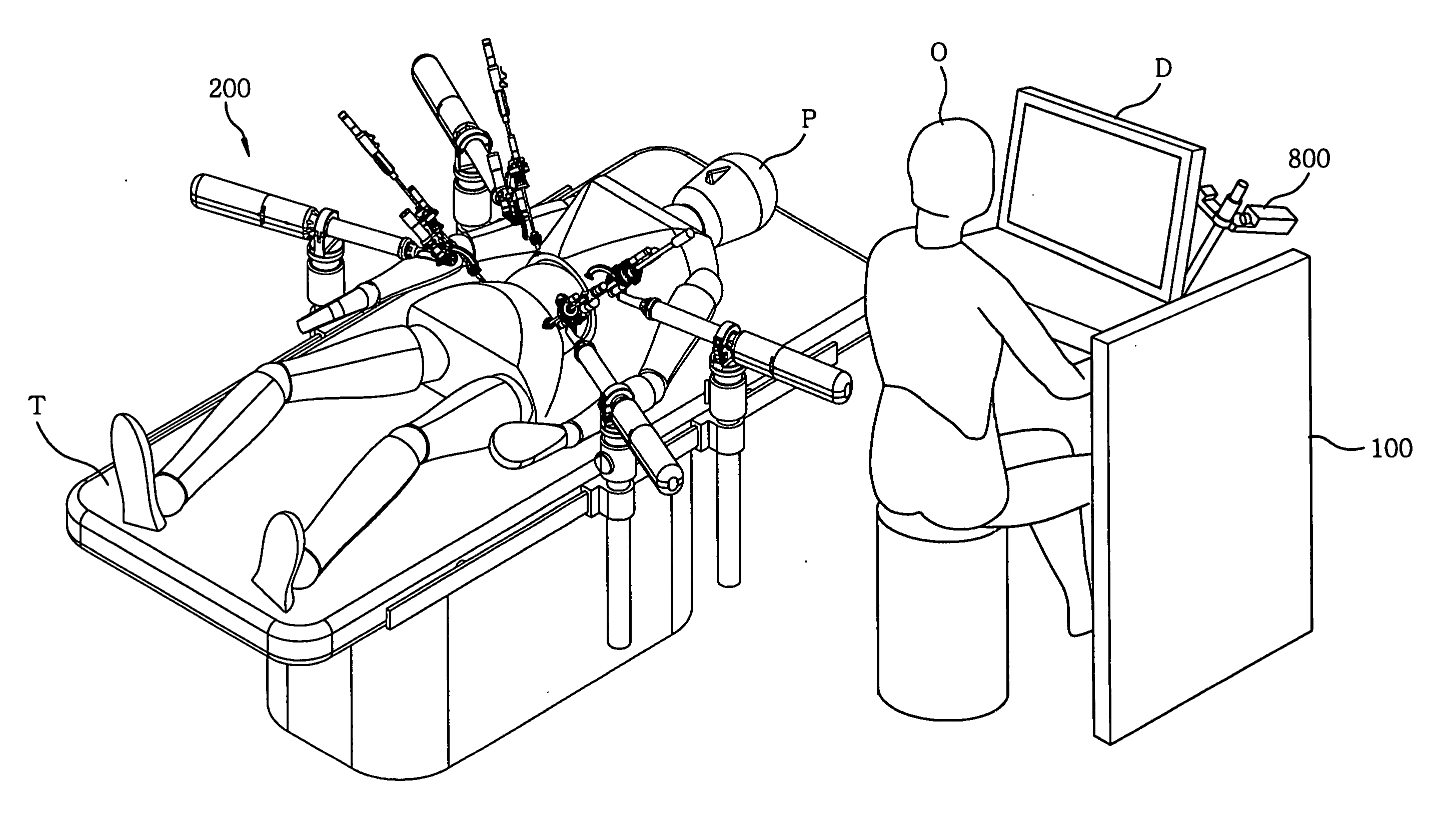
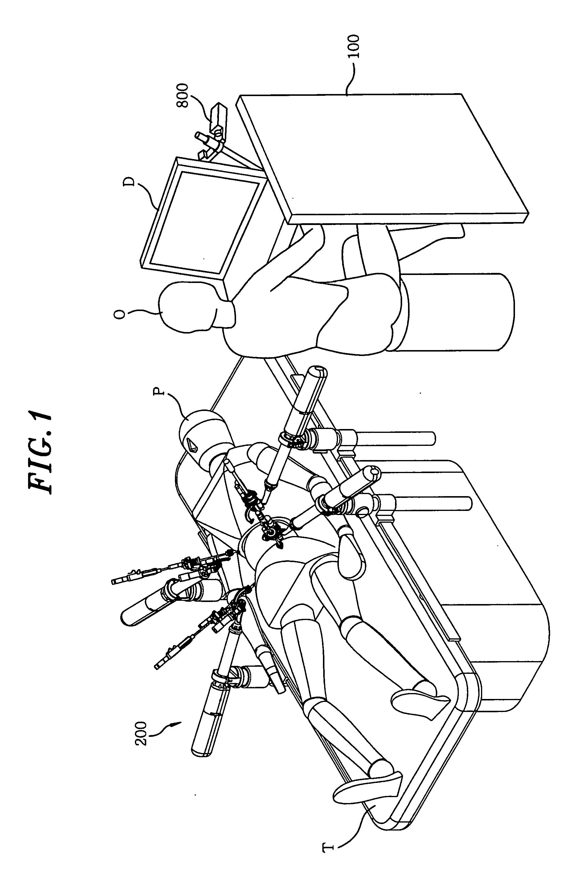
[0027]Referring to FIG. 1, the robotic surgical system includes a plurality of slave robotic units 200 for performing a surgery on a patient P lying on an operation table T; and master manipulators 800, which are installed in a control station 100, for allowing an operator O to remotely control the slave robotic units 200. The control station 100 includes a control system (not shown) for converting movements of the master manipulator 800 into electrical signals; and a display D for allowing the operator O to see surgical procedures conducted by the slave robotic units 200. At least one of the slave robotic units 200 has an endoscope (not shown) for allowing the operator O to view a surgical site through the display D while doing an operation.

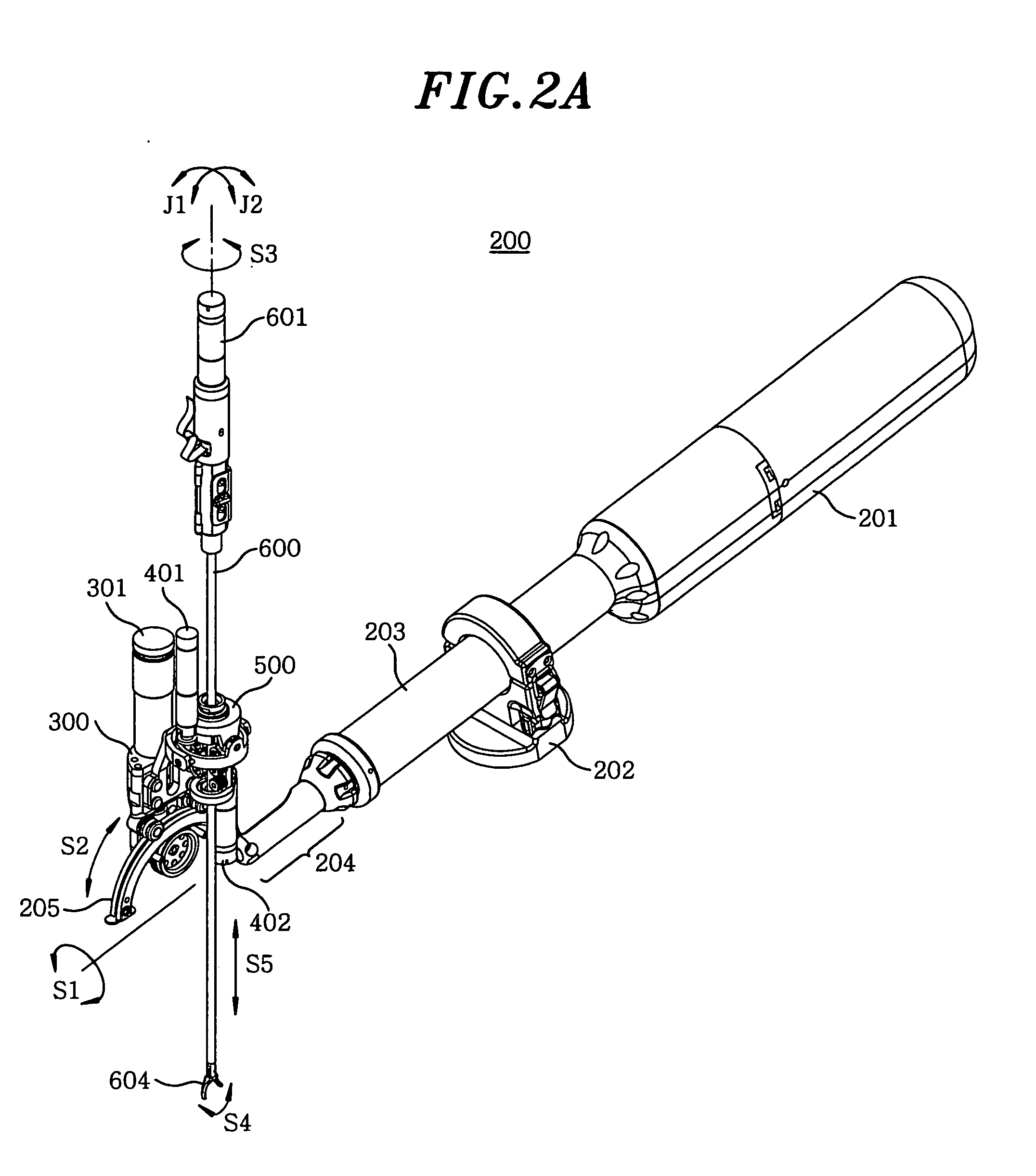
[0028]Referring to FIGS. 2A to 2C, the slave robotic unit 200...


PUM


Abstract

A robotic surgical system includes a master manipulator, slave robotic units having a surgical instrument for performing a Minimal Invasive Surgery (MIS), and a control system for electrically associating the master manipulator with the slave robotic units. The slave robotic unit includes the driving mechanisms which are more compact than those of the conventional MIS system. In use, the existing surgical instruments used in the conventional MIS procedure can be applied to the slave robotic unit. Moreover, by using the pivotal mechanism of the driving mechanisms, a pivot point of the surgical instrument is allowed to be shifted with respect to an incision of a patient. So, the patient's tissues surrounding the surgical instrument are not excessively affected by the surgical instrument during the procedure.

Description

FIELD OF THE INVENTION[0001]The present invention relates to a robotic surgical system; and, more particularly, to a robotic surgical system having a plurality of compact slave robotic arms capable of performing laparoscopic surgery in minimal invasive manner.BACKGROUND OF THE INVENTION[0002]Generally, there have been attempts to perform a minimally invasive surgical (MIS) procedure. Such MIS techniques are aimed at reducing the amount of extraneous tissue that is damaged during diagnostic or surgical procedures, thereby reducing patient recovery time, discomfort, and deleterious side effects. The most common form of such procedures is laparoscopy, which is used for minimally invasive inspection and surgery inside the abdominal cavity. To perform such MIS procedures, a surgeon needs special instruments. The surgeon passes these instruments through a small incision of an abdominal wall to a surgical site and manipulates them from outside the abdominal wall by sliding them in and out ...

Claims


Application Information

Patent Timeline
IPC IPC(8): A61B17/00
CPCA61B19/22A61B2019/2234A61B2019/2223A61B19/2203A61B34/70A61B34/30A61B34/37A61B2034/305
Inventor JO, YUNG-HOKIM, DONG-JUNCHOI, JAESOONPARK, JAE-GAHBKIM, YOUNG-WOOPARK, SANG-JAE
Owner NAT CANCER CENT
Learn More