Vehicle Speed Control System

a technology of vehicle speed control and control system, which is applied in the direction of process and machine control, instruments, navigation instruments, etc., can solve the problems of poor running stability, inability to capture sharp curves ahead, and inability to accurately predict the direction of the vehicle, so as to improve the safe feeling of the driver/passenger, stable speed control, and accurate prediction

Inactive Publication Date: 2008-03-06
CLARION CO LTD
View PDF5 Cites 63 Cited by
  • Summary
  • Abstract
  • Description
  • Claims
  • Application Information

AI Technical Summary

Benefits of technology

[0013] According to the present invention, highly stable velocity control can be implemented by: comparing a target velocity computed based on map information and a target velocity computed based on other information than the map information; selecting a lower target velocity; and controlling a vehicle velocity in accordance with the selected target velocity.
[0014] In addition, by providing a notifying part that no...

Problems solved by technology

However, in the system using the GPS, accuracy becomes markedly poor depending on the geographic features, due to occurrence of multipath or failure in satellite capture.
However, in the method disclosed in this patent document, the target velocity is corrected based on a result of reliability judgment on a road profile, and therefore, running stability may become poor depending on a road profile on which the vehicle is running.
However, if the road is flanked by walls, the sharp curve is hidde...

Method used


Image

  • Vehicle Speed Control System
  • Vehicle Speed Control System
  • Vehicle Speed Control System

Examples


first embodiment

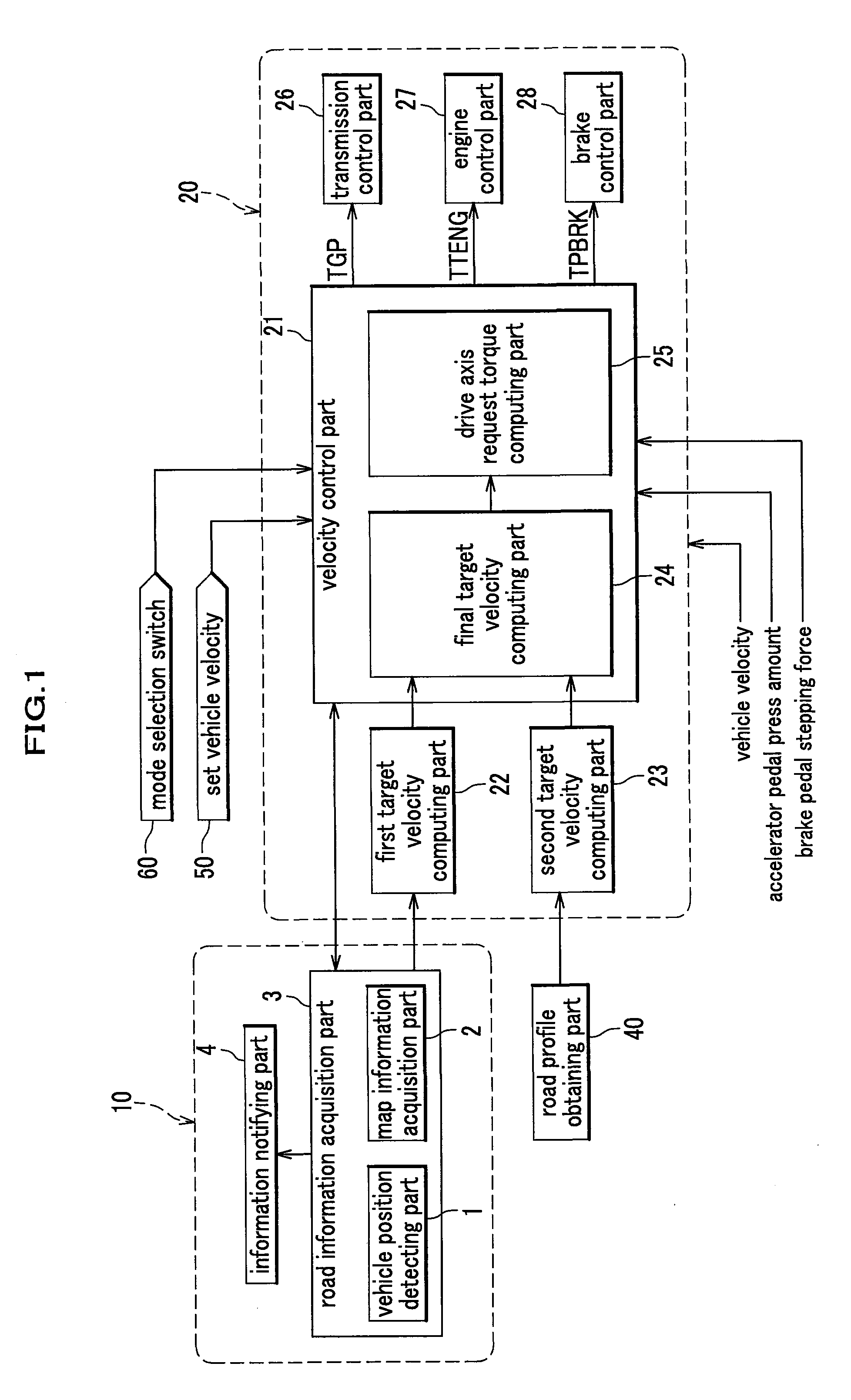
[0041]FIG. 1 is a schematic diagram showing a vehicle speed control system according to a first embodiment of the present invention.

[0042] In the following descriptions, a “first acquisition part” corresponds to, for example, a vehicle position detecting part 1. A “second acquisition part” corresponds to, for example, a map information acquisition part 2. A “first road profile estimating part” corresponds to, for example, a road information acquisition part 3. A “second road profile estimating part” corresponds to, for example, a road profile obtaining part 40. A “first target velocity calculation part” and “second target velocity calculation part” correspond to, for example, a first target velocity computing part 22 and a second target velocity computing part 23, respectively. In the following descriptions, the velocity control part 21 serves also as “road profile evaluating part”. However, the road profile evaluating part may be provided outside the velocity control part 21. The ...

second embodiment

[0163]FIG. 15 is a schematic diagram showing a vehicle speed control system according to a second embodiment of the present invention.

[0164] Configuration of FIG. 15 is substantially the same as the configuration of the first embodiment shown in FIG. 1, except that the first target velocity computing part 22, the second target velocity computing part 23 and the final target velocity computing part 24 are replaced with a first curvature radius information acquisition part 1501, a second curvature radius information acquisition part 1502 and a curvature radius target velocity computing part 1503, respectively. It should be noted that, though the first curvature radius information acquisition part 1501 and the second curvature radius information acquisition part 1502 are included in the speed controller 20, the first curvature radius information acquisition part 1501 may be included in the road information acquisition part 3, and the second curvature radius information acquisition par...

third embodiment

[0180]FIG. 17 is a schematic diagram showing a vehicle speed control system according to a third embodiment of the present invention.

[0181] Configuration of FIG. 17 is substantially the same as the configuration of the first embodiment shown in FIG. 1, except that the first target velocity computing part 22, the second target velocity computing part 23 and the final target velocity computing part 24 are replaced with a first distance information acquisition part 1701, a second distance information acquisition part 1702 and a distance target velocity computing part 1703, respectively. It should be noted that, though the first distance information acquisition part 1701 and the second distance information acquisition part 1702 are included in the speed controller 20, the first distance information acquisition part 1701 may be included in the road information acquisition part 3, and the second distance information acquisition part 1702 may be included in the road profile obtaining part...


PUM


Abstract

A vehicle speed control system includes: a unit for computing a first target velocity based on map information; a unit for computing a second target velocity based on a road profile obtained from other information than the map information (such as lane recognition using a camera); a unit for comparing the first target velocity and the second target velocity; a unit for selecting a lower target velocity therefrom; and a unit for controlling a vehicle velocity in accordance with the selected target velocity.

Description

CROSS-REFERENCE TO RELATED APPLICATIONS [0001] This application claims the foreign priority benefit under Title 35, United States Code, section 119 (a)-(d), of Japanese Patent Application No. 2006-184017, filed on Jul. 4, 2006 in the Japan Patent Office, the disclosure of which is herein incorporated by reference in its entirety. BACKGROUND OF THE INVENTION [0002] 1. Field of the Invention [0003] The present invention relates to a vehicle speed control system, and particularly to a vehicle speed control system that controls at least one of an engine, a transmission and a brake, in accordance with control parameters computed based on running environment ahead of the vehicle. [0004] 2. Description of the Related Art [0005] Japanese unexamined patent publication No. H04-236699 discloses a system for realizing stable running by: extracting a road profile (for example, curved track) from map information stored in a navigation system that detects or estimates a driving route; setting a ta...

Claims


Application Information

Patent Timeline
IPC IPC(8): G05D1/00B60T7/12B60W10/04B60W10/06B60W10/18B60W10/188B60W30/00B60W30/14B60W40/02F02D29/02G08G1/16G09B29/00G09B29/10
CPCB60W30/143B60W2550/10B60W2750/00B60W2550/402B60W2720/10B60W2550/146B60W2754/00B60W2552/30B60W2554/00B60W2556/50
Inventor IMAI, MASATOSAKAMOTO, HIROSHIOCHI, TATSUYAOKADA, TAKASHIMINOWA, TOSHIMICHISAKATA, MASAO
Owner CLARION CO LTD
Why Eureka
Try Eureka