Storage system, and data management and migration method

Inactive Publication Date: 2008-03-06
HITACHI LTD
View PDF2 Cites 8 Cited by
  • Summary
  • Abstract
  • Description
  • Claims
  • Application Information

AI Technical Summary

Benefits of technology

[0016]According to this invention, it is possible to change the access destination of the host system to a new storage apparatus without having to suspend the transmission of data between the host system and storage apparatuses.
[0017]Moreover, when migrating the access destination for the host system between different types of storage a

Problems solved by technology

However, with the existing methods for migrating the access destination for the host system to a new storage apparatus, there is a problem in tha

Method used


Image

  • Storage system, and data management and migration method
  • Storage system, and data management and migration method
  • Storage system, and data management and migration method

Examples


embodiment 1

(1) Embodiment 1

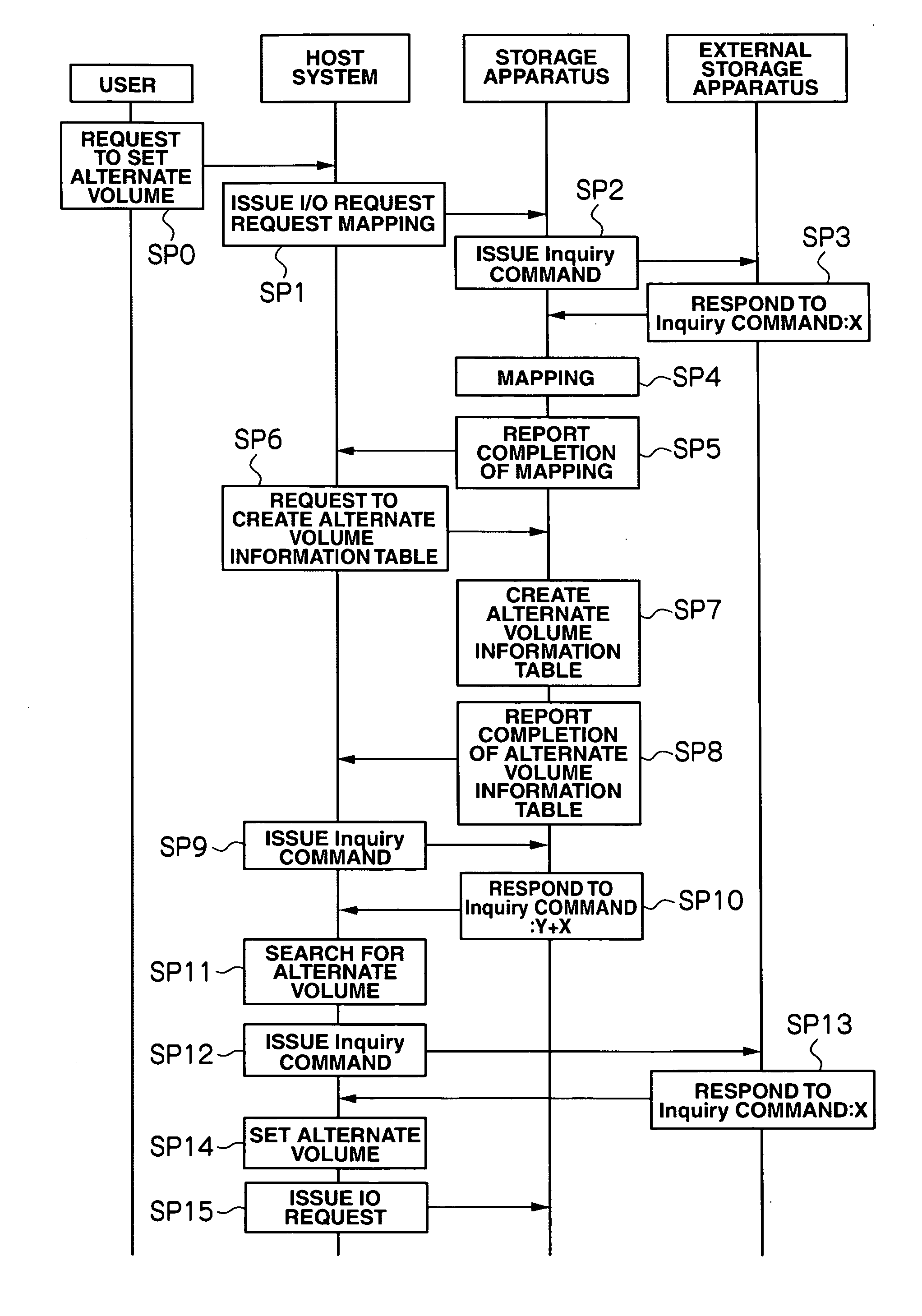
[0047](1-1) Storage System Structure in Embodiment 1

[0048]First, the storage system according to Embodiment 1 is explained below.

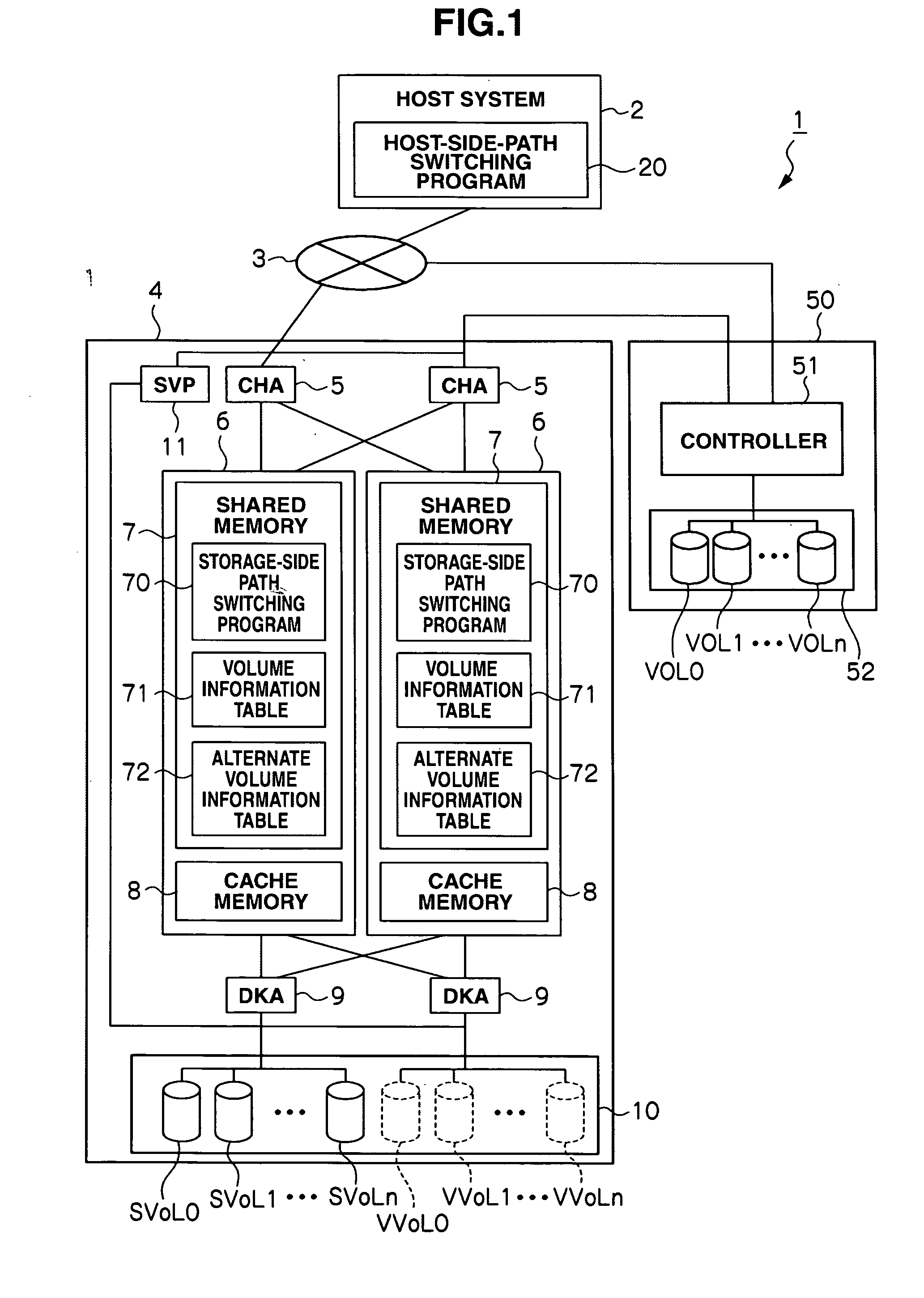
[0049]In FIG. 1, reference numeral 1 indicates the overall storage system according to Embodiment 1. In this storage system 1, a host system 2 is connected to a storage apparatus 4 via a network 3 and the storage apparatus 4 is connected to an external storage apparatus 50.

[0050]The host system 2 is a computer, for example, a personal computer, work station, or main frame, that has information processing resources such as a CPU (Central Processing Unit) and memory. It also includes information input devices (not shown in the drawing) such as a keyboard, switches, pointing device, and microphone; and information output devices (not shown in the drawing) such as a monitor display and speaker. A host-side path switching program 20 is run on the host system 2.

[0051]The network 3 is, for example, a SAN (Storage Area Network), a LAN (Local Area N...

embodiment 2

(2) Embodiment 2

[0149](2-1) Structure of Storage System in Embodiment 2

[0150]The storage system 200 according to Embodiment 2 will be explained below. In Embodiment 2, the same components as those in Embodiment 1 are given to the same reference numerals. Here, only the configurations different from those in Embodiment 1 are explained.

[0151]In FIG. 15, reference numeral 200 shows the overall storage system. In this system 200, the host system 2 is connected via the network 3 to the storage apparatus 4 (called “first storage apparatus 4” in this embodiment), which is the same as the one explained in Embodiment 1, and also to a second storage apparatus 40, and both the first and second storage apparatuses 4 and 40 are connected to the external storage apparatus 50.

[0152]Incidentally, in the explanation of Embodiment 2, first substantial volumes SVOL0-n and first virtual volumes VVOL0-n correspond to the substantial volumes SVOL0-n and virtual volumes VVOL0-n in Embodiment 1.

[0153]The s...

embodiment 3

(3) Embodiment 3

[0194](3-1) Structure of Storage System in Embodiment 3

[0195]The storage system 300 according to Embodiment 3 is explained below. In this embodiment, the same components as those in Embodiments 1 and 2 are given the same reference numerals. Only configurations different from those in Embodiment 2 will be explained.

[0196]In the storage system 300 according to Embodiment 3, in addition to the storage apparatuses included in the storage system 200 in Embodiment 2, a different-type of storage apparatus, i.e., a third storage apparatus 60 is also connected to the first storage apparatus 4 and external storage apparatus 50.

[0197]Hard disk drives (not shown in the drawing) in the third storage apparatus 60 provide storage areas, for which a plurality of logical volumes (not shown in the drawing) are set. One of the attributes of the logical volumes is a virtual volume (not shown in the drawing). A virtual volume is a virtual logical volume that does not exist physically. It...


PUM


Abstract

A storage system or data management and migration method enabling migration of an access destination for a host system without having to stop the transmission of data between the host system and storage apparatuses. The storage system includes: a host system that issues a data read/write request; an external storage apparatus that provides an external logical volume for storing the data; and a first storage apparatus that creates a first virtual logical volume. In this system, the host system makes a request to the first storage apparatus to map volume information composed of the management information for the external logical volume; in response to the mapping request, the first storage apparatus maps the volume information for the external logical volume onto the first virtual logical volume and sends the volume information for the external logical volume and first virtual logical volume to the host system; based on the volume information for the external logical volume sent from the first storage apparatus, the host system searches for any virtual logical volume having the same volume information as the volume information for the first virtual logical volume or external logical volume, and sets the virtual logical volume searched for in this search as an alternate volume for receiving requests to read/write data from/to the external logical volume.

Description

CROSS-REFERENCES TO RELATED APPLICATIONS[0001]This application relates to and claims priority from Japanese Patent Application No. 2006-232727, filed on Aug. 29, 2006, the entire disclosure of which is incorporated herein by reference.BACKGROUND[0002]1. Field of the Invention[0003]The invention relates generally to a storage system and data management and migration method, and is suitable for use in a storage system where volumes have to be migrated between different types of storage apparatuses.[0004]2. Description of Related Art[0005]In storage systems handling a large amount of data, the data has been managed using large-capacity storage apparatuses provided separately from host systems.[0006]The storage apparatuses used in these storage systems have many hard disk devices arranged in arrays and are configured so that the hard disk devices are used according to the RAID (Redundant Array of Independent Inexpensive Disks) system. These hard disk devices provide physical storage are...

Claims


Application Information

Patent Timeline
IPC IPC(8): G06F13/00G06F12/00
CPCG06F3/0605G06F3/0647G06F3/067
Inventor OZAKI, SATORUNAKAGAWA, YOSHIHITO
Owner HITACHI LTD
Why Eureka
Try Eureka