Multi-layer cable design and method of manufacture

a multi-layer cable and cable technology, applied in the direction of insulated cables, communication cables, electrocardiac procedures, etc., can solve the problems of flexing and bending, affecting the performance of the cable, so as to achieve the effect of more flexibility without sacrificing performan

Inactive Publication Date: 2008-03-13
RAZAVI ALI
View PDF7 Cites 231 Cited by
  • Summary
  • Abstract
  • Description
  • Claims
  • Application Information

AI Technical Summary

Benefits of technology

[0017] It is an object of the present invention to provide a cable which is lightweight.
[0018] It is an object of the present invention to provide a cable which is flexible.
[0019] It is another object of the present invention to provide an economically manufactured lightweight cable.
[0021] It is another object of the present invention to provide a cable which is much more flexible without sacrificing performance.

Problems solved by technology

Electric signals passing through the conductors tend to ‘bleed’ through the insulator and dissipate with distance.
Again, using more dielectric minimizes this cross-talk, however makes the cables thicker and mechanically more difficult to carry, flex and bend.
These provide greater shielding against cross-talk; however, these tend to be even mechanically cumbersome than cables which are not coaxial due to the geometry.
This invention suffers from a lack of performance when the carbon fibers break and cause electrical discontinuities.

Method used


Image

  • Multi-layer cable design and method of manufacture
  • Multi-layer cable design and method of manufacture
  • Multi-layer cable design and method of manufacture

Examples


Embodiment Construction

Multilayer Cable Design & Method of Manufacturing

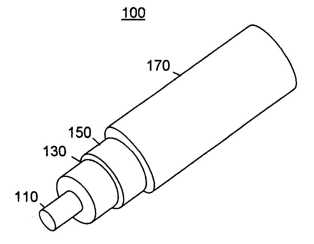
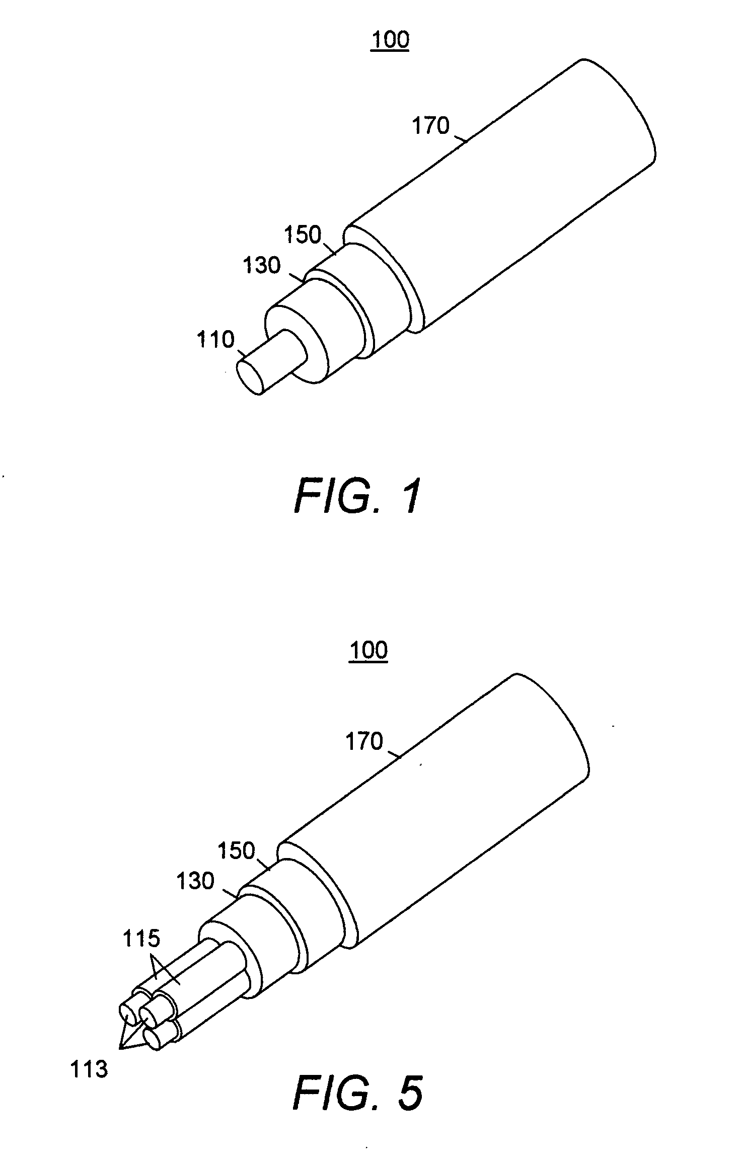
[0029] The present invention results in lightweight, flexible wires and cables designed for low signal loss for their individual applications. These wire or cables may be embodied as a coaxial cable with central conductor, a pair of wire conductors, ribbon cables with many conductors and other known cable designs.

[0030] Traditionally, the design of electronic cables involved a trade-off between the electrical properties such as high signal propagation and low attenuation and the mechanical or bending properties of the cable.

[0031] The present invention results in multilayer cables designed to reduced weight but retain their electrical and mechanical performance properties.

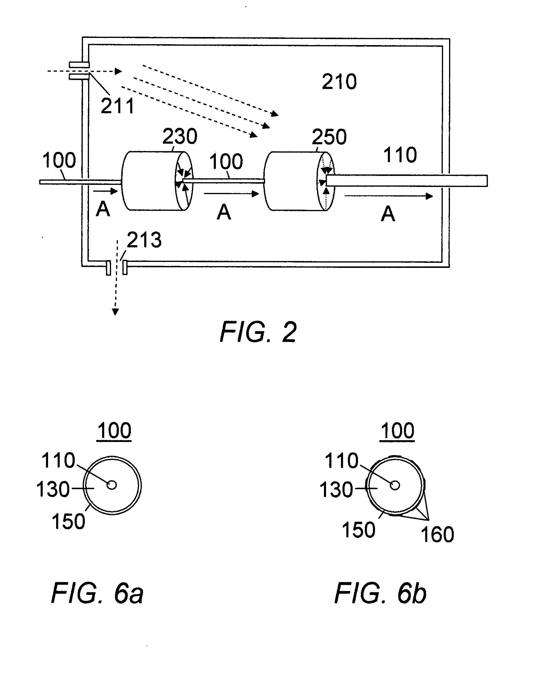
[0032] The present invention combines several areas of innovative micro-fabrication technologies in a novel design. The cables are manufactured using thin film technology.

I. Thin Film Continuous Outer Conductor

[0033]FIG. 1 is a perspective view of one embodime...


PUM

PropertyMeasurementUnit
thicknessaaaaaaaaaa
thicknessaaaaaaaaaa
flexibleaaaaaaaaaa

Abstract

A novel method of designing and fabricating flexible and lightweight cable [100] having a central conductor [110], a dielectric layer [130], an outer conductor [150] and an insulation coating [170] using thin film technology is disclosed. The dielectric layer [130] is ‘grown’ on dielectric layer [130] using electrophoretic deposition to a specified thickness, based upon its intended use. It may include nano-diamonds. Ion beam assisted deposition is used to metalize the cable dielectric layer [130]. This may be ion beam assisted sputtering, ion beam assisted evaporative deposition or ion beam assisted cathodic arc deposition. In an alternative embodiment, the outer conductor may be etched to provide greater flexibility, or to add a piezoelectric layer. The central conductor [110] may be created from dielectric fibers [113] which are metalized as described above. The piezoelectric layer added to create ultrasonic transducer cables.

Description

CROSS REFERENCE TO RELATED APPLICATIONS [0001] This patent application is a continuation-in-part application and claims priority from U.S. Patent Application 60 / 840,566 filed Aug. 28, 2006 by the same inventor, Dr. Ali Razavi.BACKGROUND OF THE INVENTION [0002] 1. Field of the Invention [0003] The present invention relates to a thin, lightweight and flexible electronic cable. [0004] 2. Discussion of Related Art [0005] Electric and electronic wires or cables include one or more conductors with a dielectric insulation material electrically insulating them from the other conductors or other electrically conducting objects. Electric signals passing through the conductors tend to ‘bleed’ through the insulator and dissipate with distance. The greater the amount of dielectric, the less the dissipation. [0006] Since wires are bundled with wires carrying different signals, there is the effect of “cross-talk” in which signals pass through the insulation and are picked up on adjacent wires. [00...

Claims


Application Information

Patent Timeline
Patent Type & Authority Applications(United States)
IPC IPC(8): H01B11/00B44C1/22H01B7/02H05K9/00C23C14/00
CPCH01B13/225
Inventor RAZAVI, ALI
Owner RAZAVI ALI
Why Eureka
Try Eureka