Elevator system
- Summary
- Abstract
- Description
- Claims
- Application Information
AI Technical Summary
Benefits of technology
Problems solved by technology
Method used
Image

Examples
Embodiment Construction
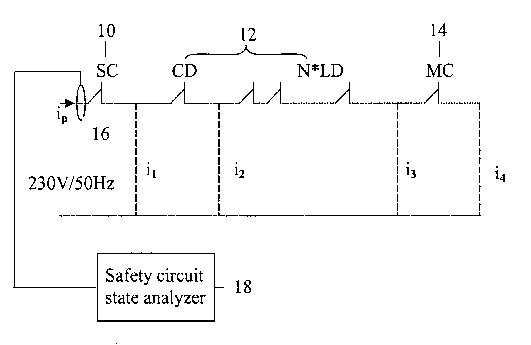
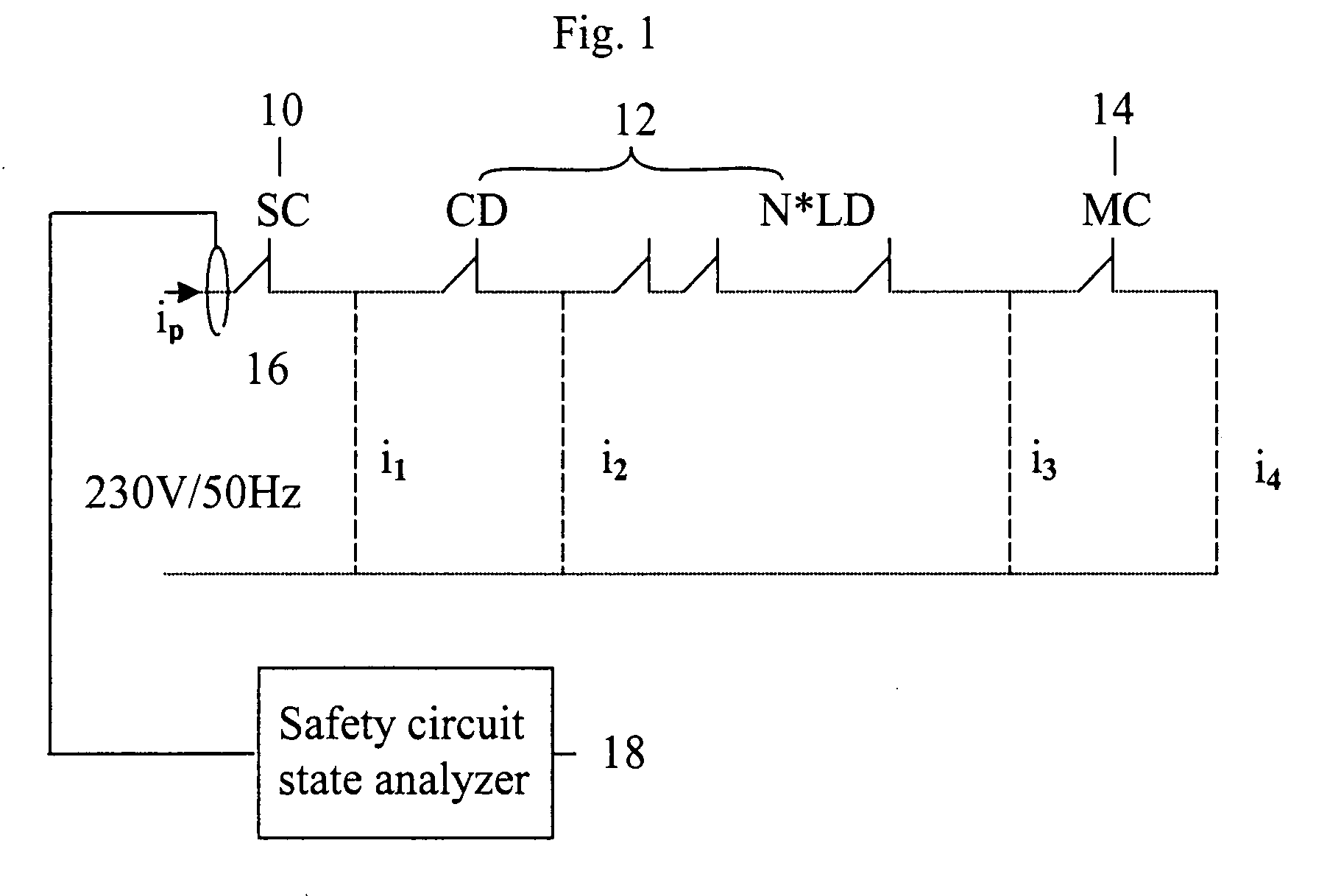
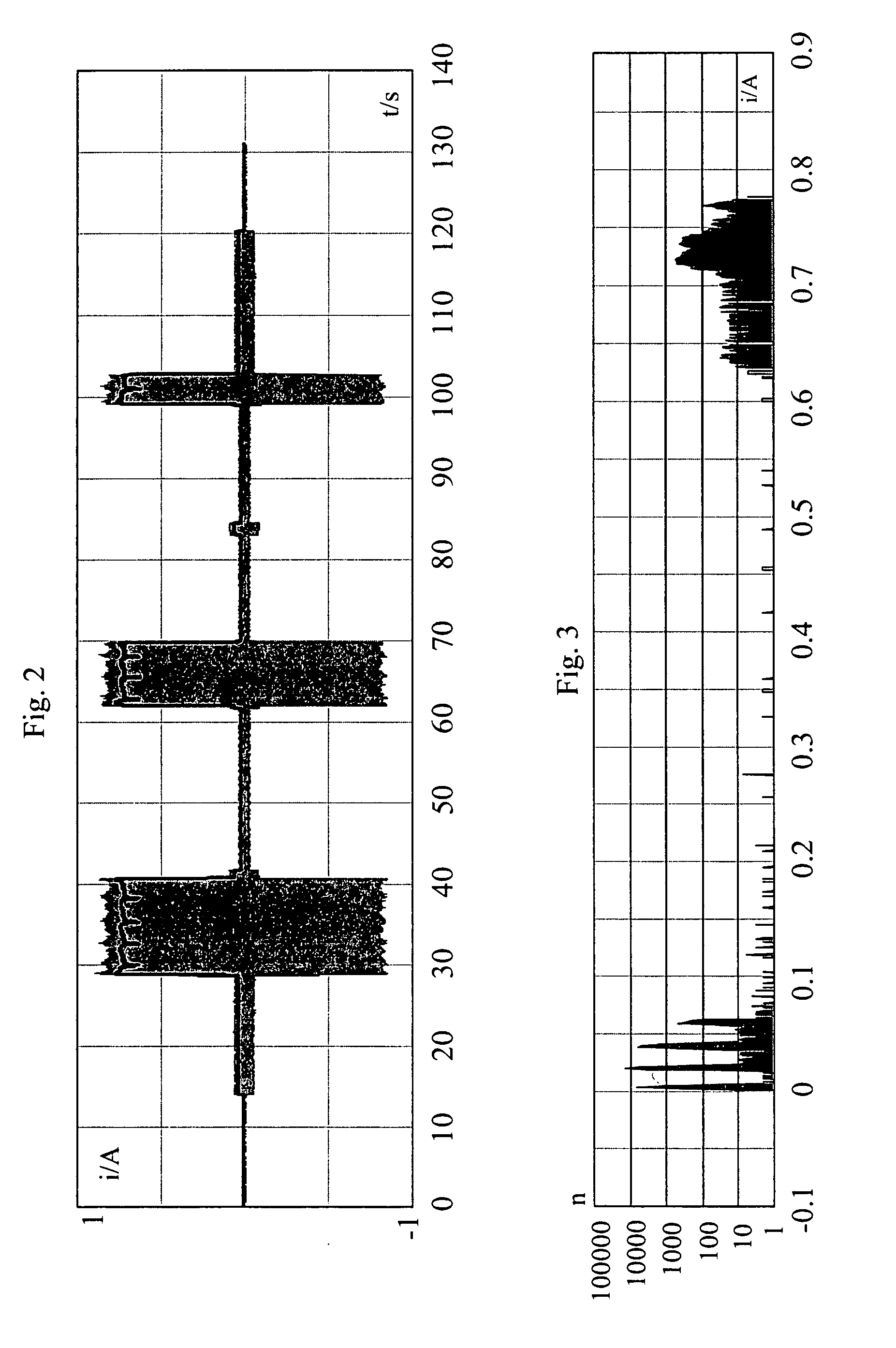
[0026] In the following, the invention will be described in detail with reference to FIGS. 1-4. FIG. 1 presents a safety circuit with the safety circuit currents i1, i2, i3 and i4 indicated according to the invention at different points in the circuit.
[0027] In the safety circuit presented in FIG. 1, SC 10 represents the static circuit of the safety circuit. Switch CD 12 represents the car door switch, and switches N*LD 12 represent the landing door switches. The number of levels is N, depending on how many floors the elevator comprises. Switch MC 14 corresponds to the main contactor.
[0028] The total current ip at point p is obtained as follows: ip=SC·i1+CD·i2+i3·∏k=1NLDk+MC·i4,
where switches SC, CD, LD and MC get the value of 0 or 1.
[0029] From the magnitude of the total current, the state of the safety circuit at each instant of time can be unambiguously deduced. The possible states of the safety circuit are defined in Table 1 below:
TABLE 1Safety circuitcurrent atOperation...
PUM
 Abstract
Description
Claims
Application Information