Motor and disc drive with motor

a disc drive and motor technology, applied in the direction of sliding contact bearings, instruments, record information storage, etc., can solve the problems of insufficient pressure insertion intensity weak bearing structure, and inability to locate the taper seal portion ts in the vicinity of the center area of the bearing structure, etc., to achieve high impact resistance, increase the reliability of the motor, and increase the strength of the pressure insertion strength

Inactive Publication Date: 2008-03-13
ALPHANA TECH CO LTD
View PDF7 Cites 19 Cited by
  • Summary
  • Abstract
  • Description
  • Claims
  • Application Information

AI Technical Summary

Benefits of technology

[0020] According to the present invention, the sleeve and the sleeve holder are surrounded by the inner body which is fixed in the inside of the annular wall portion of the rotor hub. This allows a gap, which corresponds to a taper seal portion disclosed in Japanese Patent Application Laid-Open No. 2006-183734, to be formed by adjusting an inner diameter of the inner body and outer diameters of the sleeve and the sleeve holder, independent of an outer diameter of the flange portion of the sleeve. This configuration allows the gap to be disposed at a rotor spindle side, which prevents the lubrication oil from spreading outside due to centrifugal force.
[0021] Also, the first end portion of the inner body abuts the inner surface of the rotor hub. This allows the annular wall portion of the rotor hub to hold the inner body at a whole inner circumference surface of the annular wall portion, which increases pressure-insertion strength. Therefore, the motor has high impact resistance and reliability of the motor increases.
[0022] Further, the inner body surrounds the sleeve holder. Therefore, a bearing unit which is formed by assembling the inner body, the sleeve and the sleeve holder, can be built into the annular wall portion of the rotor hub by only pr

Problems solved by technology

However, even if the thrust load is supported at the thrust bearing portion, there is a problem that the bearing structure is weak with respect to thrust force acting in a direction in which the rotor comes out of the spindle motor because force acting against the direction in which the rotor comes out of the spindle motor is only magnetic force of a magnet.
However, in reality, it is impossible to locate

Method used


Image

  • Motor and disc drive with motor
  • Motor and disc drive with motor
  • Motor and disc drive with motor

Examples


first exemplary embodiment

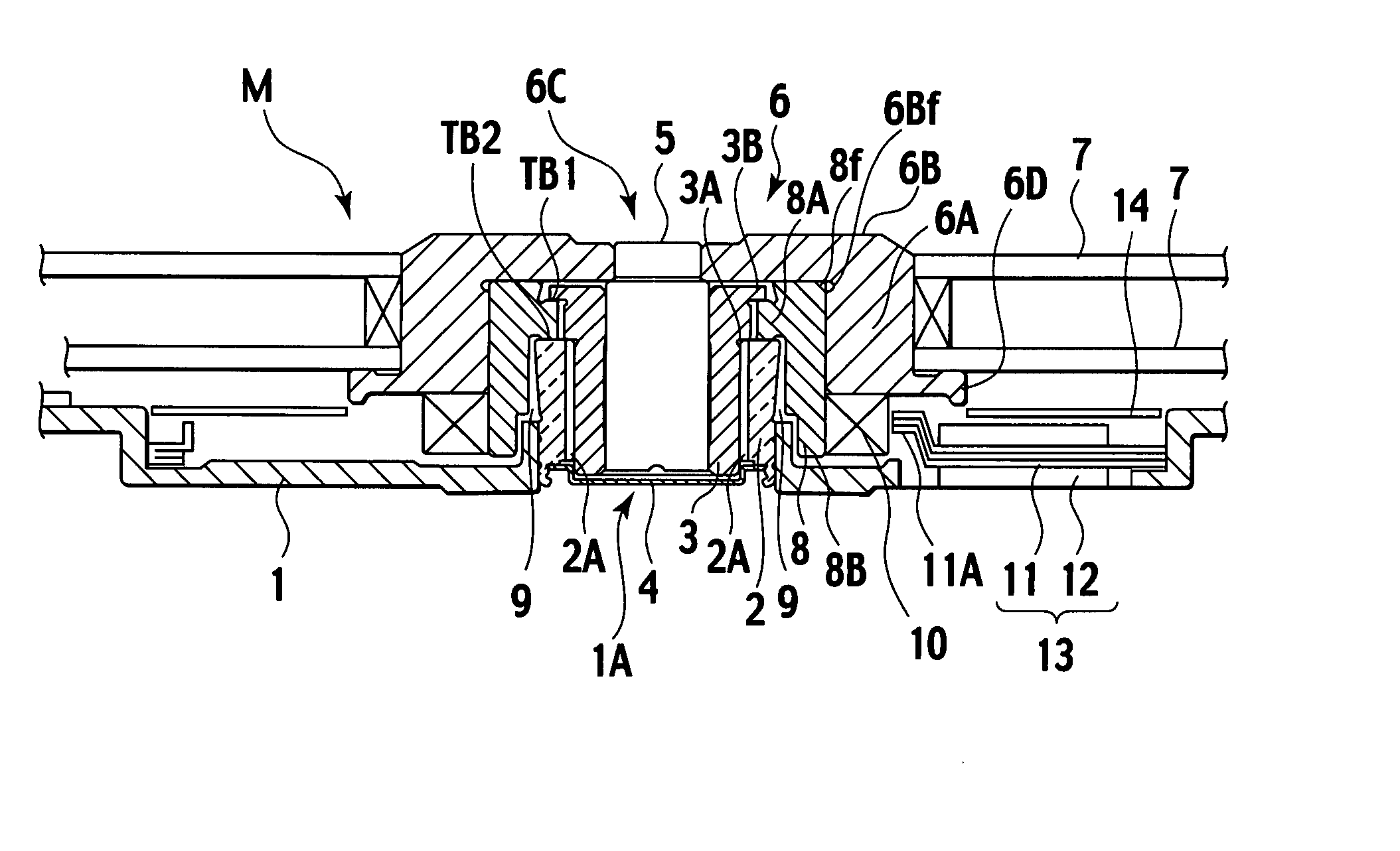
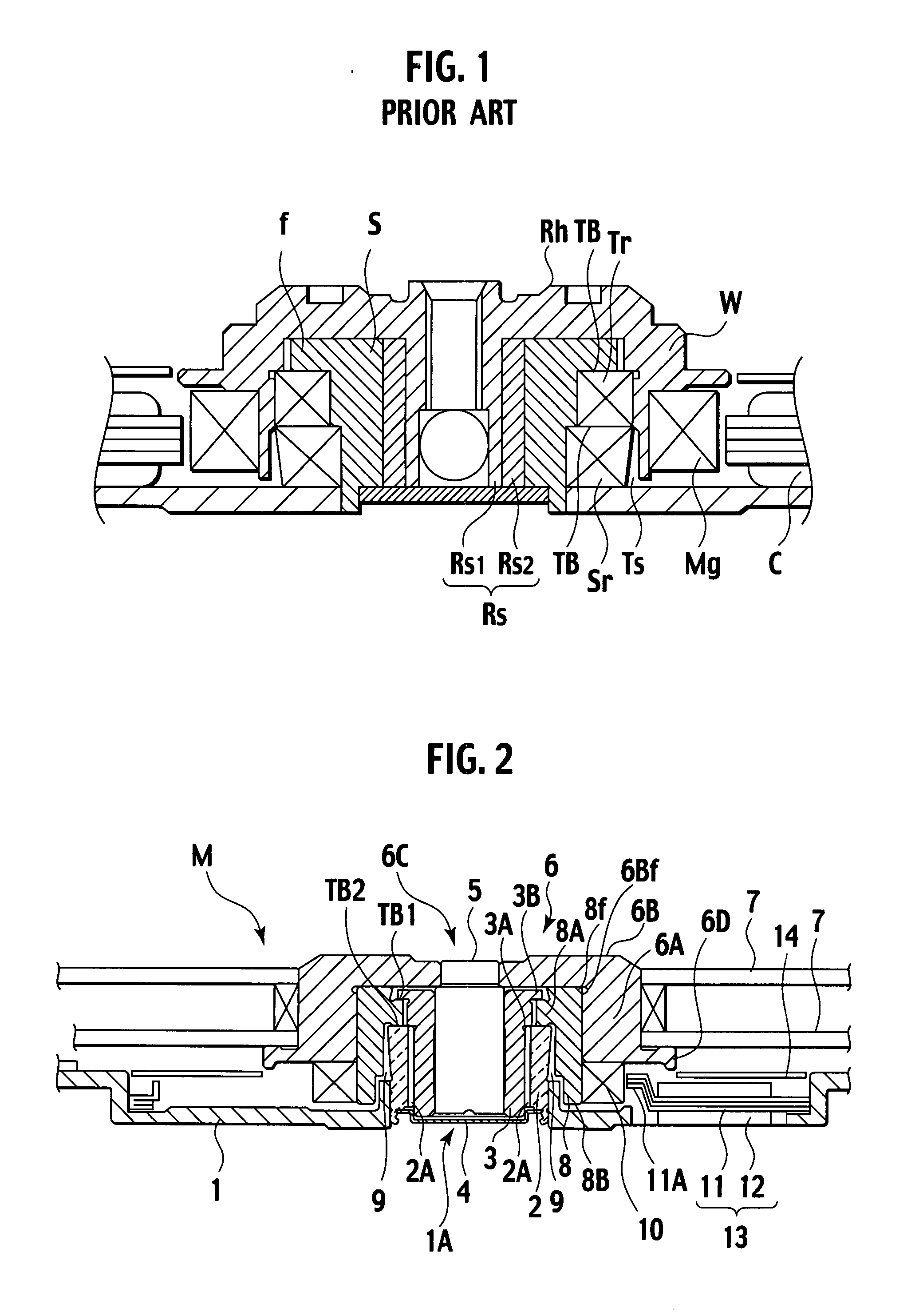
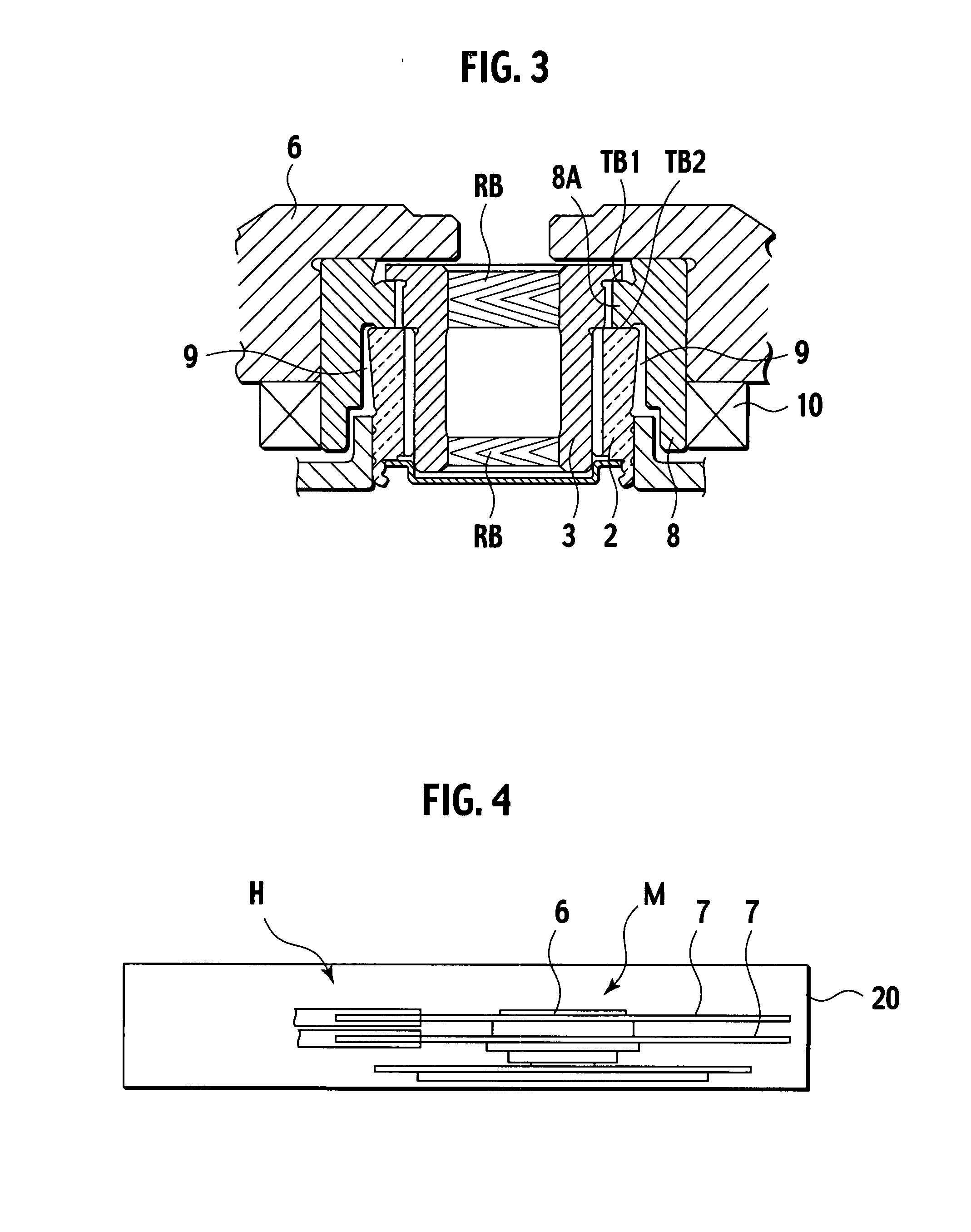
[0029] A motor (electric motor) according to a first exemplary embodiment of the present invention will be described below in detail, with reference to FIGS. 2 to 4.

[0030] As shown in FIG. 2, a motor M comprises a motor base 1, a sleeve holder 2, a sleeve 3, a seal plate 4, a rotor spindle 5, a rotor hub 6, an inner body 8, a taper seal portion 9, a field magnet 10, an armature 13 and a magnetic shield 14. The motor M is built into a disc drive (not shown in FIGS. 2 and 3) as a disc drive spindle motor configured to rotate a hard disc.

[0031] The motor base 1 forms a stator and has a center hole 1A at a center portion thereof. The motor base 1 is formed by press work for pressing an aluminum plate. The sleeve holder 2 has a cylindrical shape and an inner hole at a center portion thereof. The sleeve holder 2 is fixed into the center hole 1A with an adhesive material. The sleeve 3 has a cylindrical shape and an inner hole at a center portion thereof. The sleeve 3 is pressure-inserted...

second exemplary embodiment

[0048] A motor (electric motor) according to a second exemplary embodiment of the present invention will be described below in detail, with reference to FIG. 5.

[0049] A motor M′ according to the second exemplary embodiment is an outer rotor type motor. In contrast, the motor M according to the first exemplary embodiment is an inner rotor type motor. As shown in FIG. 5, the motor M comprises a motor base 101, the sleeve holder 2, the sleeve 3, the seal plate 4, the rotor spindle 5, a rotor hub 106, the inner body 8, the taper seal portion 9, a field magnet 110 and an armature 113. It is noted that the sleeve holder 2, the sleeve 3, the seal plate 4, the rotor spindle 5, the inner body 8 and the taper seal portion 9 are the same as those of the motor M.

[0050] The motor base 101 forms a stator and has a center hole 101A at a center portion thereof. The motor based 101 is formed by a die-cast molding etc. The sleeve holder 2 is fixed into the center hole 101A with an adhesive material...


PUM


Abstract

A motor includes a sleeve, a sleeve holder, a rotor hub and an inner body. The sleeve has a flange portion on an outer circumference portion thereof. The sleeve holder holds the sleeve. The rotor hub has an annular wall portion. The inner body is fixed in an inside of the annular wall portion so as to surround the sleeve and the sleeve holder. The inner body has an annular protrusion portion which is sandwiched between the flange portion and one end portion of the sleeve holder on an inner circumference portion of thereof. A first thrust bearing portion in which a lubrication agent is filled is formed between the annular protrusion portion and the flange portion. A second thrust bearing portion in which the lubrication agent is filled is formed between the annular protrusion portion and the one end portion of the sleeve holder.

Description

BACKGROUND OF THE INVENTION [0001] 1. Field of the Invention [0002] The present invention relates to a motor employed in a disc drive such as a hard disc drive (HDD), as a drive source of the disc drive for driving a disc such as a compact disc (CD), a compact disc read only memory (CD-ROM) or a digital versatile disc (DVD). [0003] 2. Description of the Related Art [0004] Recently, there is a spindle motor with a fluid dynamic bearing in a dynamic pressure type as a rotary drive source for a disc which is an information record medium. The spindle motor is configured to firmly attach a sleeve on a motor base which forms a stator and to fill lubrication oil in a gap between the sleeve and a rotary shaft. The spindle motor has the following advantageous features: (1) the load facility is large; and (2) the high-speed capability is excellent. [0005] A bearing structure of the spindle motor is disclosed in Japanese Patent Application Laid-Open No. 2004-328926. In the bearing structure, a...

Claims


Application Information

Patent Timeline
IPC IPC(8): H02K7/08
CPCF16C17/026F16C17/10F16C2370/12G11B19/2036H02K7/085F16C33/107H02K29/00G11B19/20
Inventor KODAMA, MITSUOYAMADA, TAKUJINAGAOKA, MATOMO
Owner ALPHANA TECH CO LTD
Why Eureka
Try Eureka