Radar Device

a radar device and antenna module technology, applied in the direction of measurement devices, using reradiation, instruments, etc., can solve the problems of inability to achieve compact and light structures, inability to employ such structures as general in-vehicle electronic devices, and cost increase, so as to efficiently automate and execute the assembling work, reduce the size of the radar device, and reduce the cost

Inactive Publication Date: 2008-03-13
HITACHI LTD
View PDF27 Cites 33 Cited by
  • Summary
  • Abstract
  • Description
  • Claims
  • Application Information

AI Technical Summary

Benefits of technology

[0021]In accordance with the present invention, since it is possible to efficiently cool the antenna module, it is possible to downsize the radar device, and it is possible to assemble the housing, the control circuit board and the rear cover in order from one side to the front cover in which the antenna module and the radome are fixed to the opening portion. Accordingly, it is possible to efficiently automate and execute the assembling work of the radar device, and it is possible to achieve cost reduction.

Problems solved by technology

Further, in the conventional radar device, since the electric connection between the control circuit portion existing on the back surface of the ground potential metal layer and the high-frequency circuit portion existing on the front surface is formed by forming the through hole in the ground potential metal layer, and connecting by the core wire coated by the glass layer, and the connector is attached to the housing by the O-ring and the screw, it is complicated to attach the connector to the housing, connect between the control circuit boards and connect the control circuit board and the antenna module, and it is impossible to achieve a compact and light structure and a cost increase is caused as well as it is hard to automate an assembly.
On the other hand, in order to automatically assembling the radar device, it is desirable to assemble the constituting members in order from one side, however, since it is necessary to expose the antenna to the front surface in the radar, it is impossible to employ such a structure as a general in-vehicle electronic device as it is.

Method used


Image

  • Radar Device
  • Radar Device
  • Radar Device

Examples


Embodiment Construction

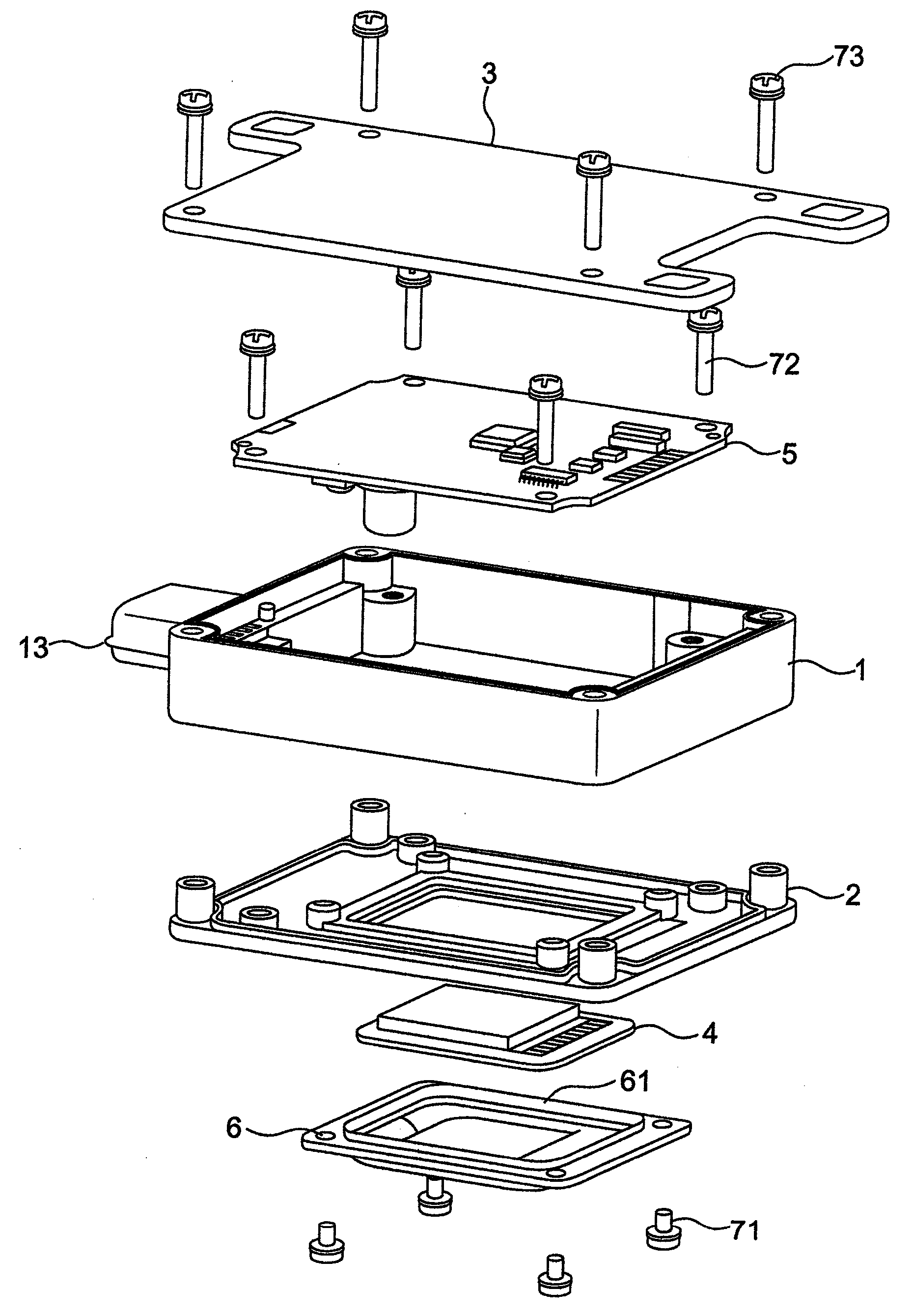
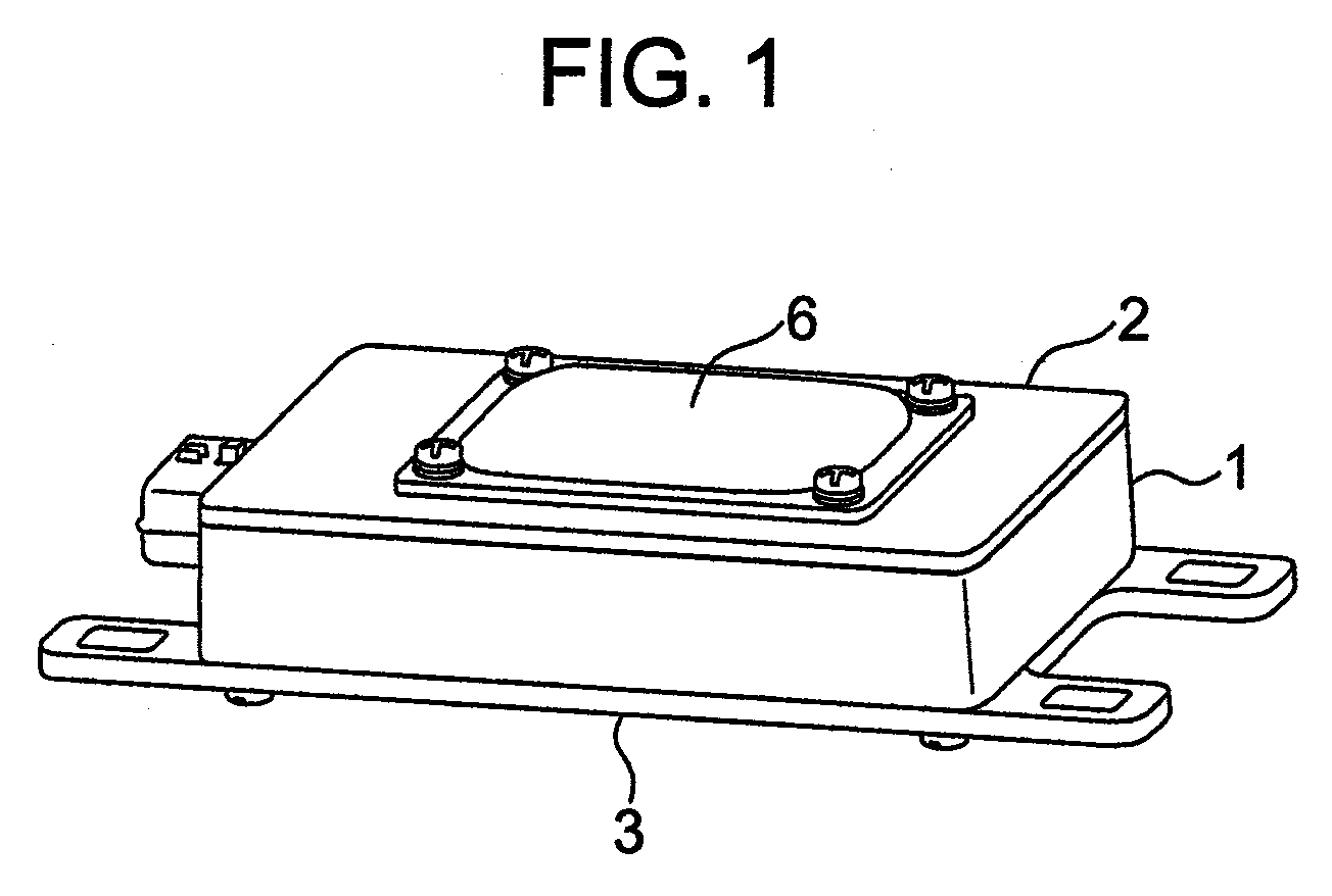
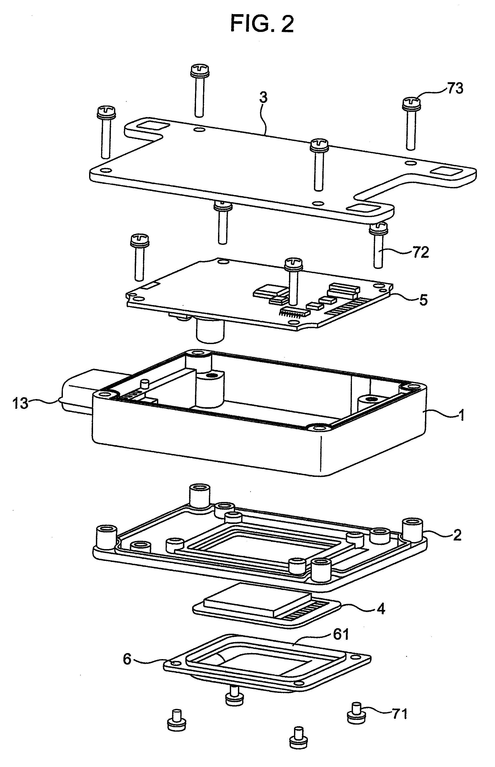
[0031]A description will be given of a radar apparatus corresponding to an embodiment in accordance with the present invention with reference to the accompanying drawings. FIG. 1 is an assembled perspective view of the radar apparatus in accordance with the present embodiment, FIG. 2 is an exploded perspective view of the radar apparatus in accordance with the present embodiment, and FIG. 3 is a cross sectional view of the radar apparatus in accordance with the present embodiment.

[0032]The radar device is constituted by a housing 1, a front cover 2, a rear cover 3, an antenna module 4 transmitting and receiving an electric wave, a control circuit board 5, and a radome 6. The antenna module 4 has a known structure, emits the electric wave and receives a reflected electric wave. The radome 6 is structured by a material having a good electric wave permeability, and a narrow convex groove 61 is formed in an outer periphery.

[0033]FIG. 4 is a plan view showing details of a first embodimen...


PUM


Abstract

In a radar device, in order to make it simple to attach a connector to a housing and connect a control circuit board to an antenna module, to make it possible to automate assembly, and to achieve downsizing and weight reduction, the radar device comprises a resin housing having upper and lower opening portions, and a control circuit board attached to the resin housing, a metal front cover and a metal rear cover are arranged so as to close the upper and lower opening portions of the resin housing, an opening portion is formed in the metal front cover, and an antenna module is arranged in the opening portion so as to be firmly attached, whereby the radar device can be assembled from one side, it is possible to improve efficiency of assembling work and it is possible to achieve downsizing and cost reduction of the radar device.

Description

FIELD OF THE INVENTION[0001]The present invention relates to a radar device which is mounted on a motor vehicle and is used for a safety control of the motor vehicle such as to detect an object in back and forth and right and left directions of the motor vehicle or the like.DESCRIPTION OF RELATED ART[0002]There has been known an in-vehicle electric wave type radar device which measures a distance or a relative speed to a vehicle, an obstacle and the like on back and forth and right and left sides, by using a mill wave band (60 to 77 GHz) electric wave having a small attenuation of an electric wave beam even in a bad weather in which a fog exists, and reaching a great distance.[0003]As the in-vehicle electric wave type radar device mentioned above, there are structures shown in JP-A-10-261917 and JP-A-2001-324561.[0004]The radar device shown in JP-A-10-261917 is structured such that an antenna, a high-frequency circuit portion and a control circuit portion are piled up in this order ...

Claims


Application Information

Patent Timeline
Patent Type & Authority Applications(United States)
IPC IPC(8): G01S13/00G01S13/931
CPCG01S7/032H05K7/20436G01S2007/027G01S13/931H05K7/20854G01S7/027
Inventor OUCHI, SHIROISONO, TADASHIMATSUURA, KAZUOSASADA, YOSHIYUKI
Owner HITACHI LTD
Why Eureka
Try Eureka