
Optical head device

a head device and optical head technology, applied in the field of optical head devices, can solve the problems of inability to perform defocus adjustment by utilizing the above-mentioned method, and reduce the signal quality

Inactive Publication Date: 2008-03-13
SANKYO SEIKI MFG CO LTD
View PDF3 Cites 2 Cited by
  • Summary
  • Abstract
  • Description
  • Claims
  • Application Information

AI Technical Summary

Benefits of technology

[0008]In view of the problems described above, an embodiment of the present invention may advantageously provide an optical head device in which focusing positions of return light beams of two laser beams to a light receiving element are capable of being coincided with each other even when a twin laser light source is used.

Problems solved by technology

However, in an optical head device provided with a twin laser light source, when a focusing error signal is to be detected by an astigmatism method, there are the following problems.
However, when a twin laser light source is used, since two laser beam emitting elements are integrated with each other, defocus adjustment by utilizing the above-mentioned method is unable to be performed.
However, when the twin laser light source is used, in addition to the problem of the above-mentioned axial chromatic aberration, two laser beam emitting elements are disposed apart about 110 μm from each other.
Accordingly, when the twin laser light source is used, a difference between focus error offsets of the respective wavelengths becomes large and thus a servo-control is not performed satisfactory to cause signal quality to reduce.

Method used


Image

  • Optical head device
  • Optical head device
  • Optical head device

Examples


Embodiment Construction

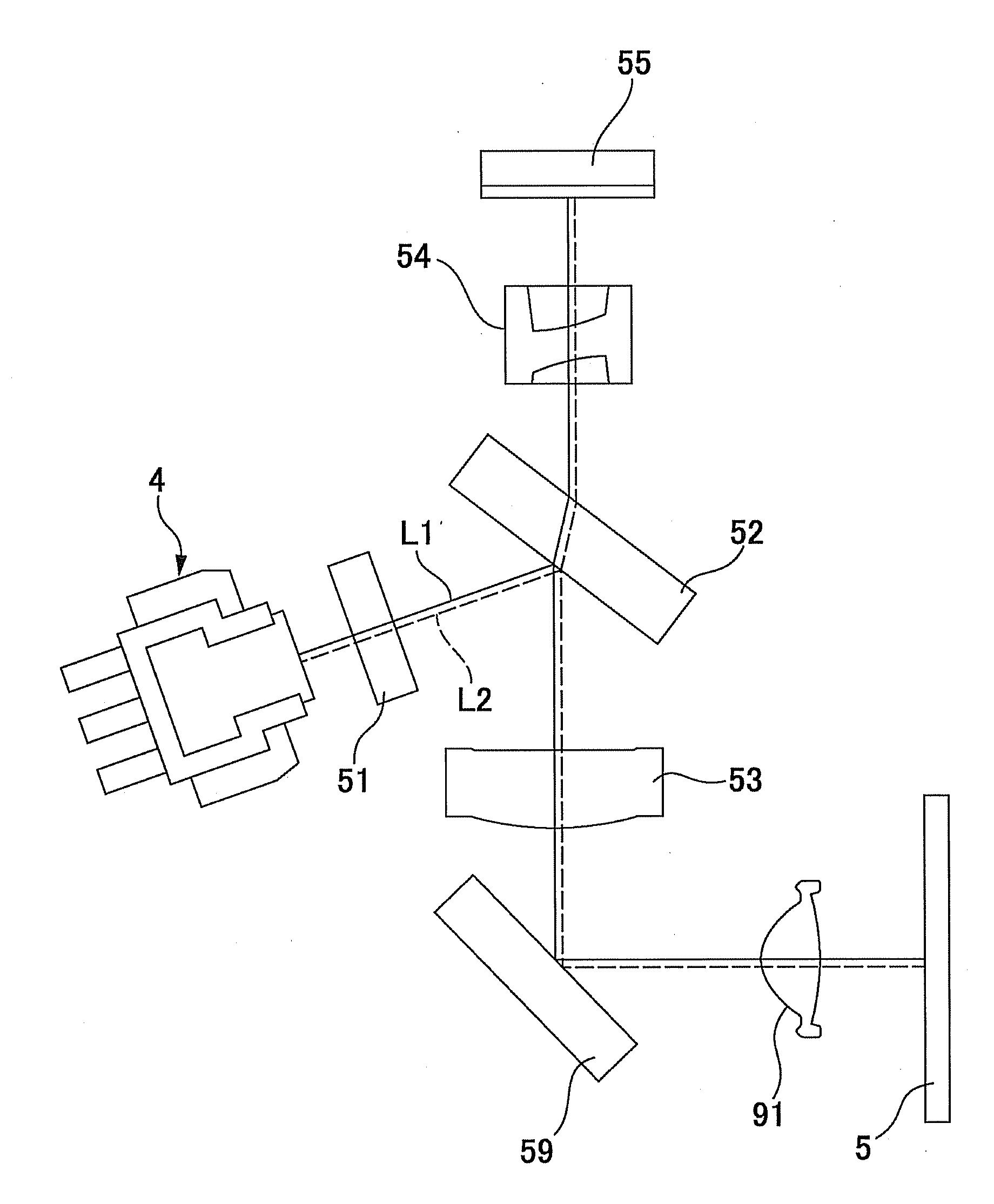
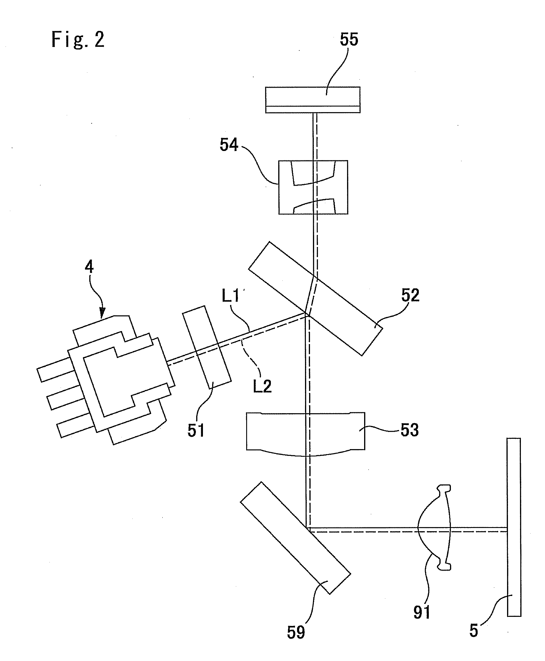
[0017]An optical head device in accordance with an embodiment of the present invention will be described below with reference to the accompanying drawings. In the following description, a disposed side of an objective lens is defined as an upper face side and its opposite side is defined as an under face side.

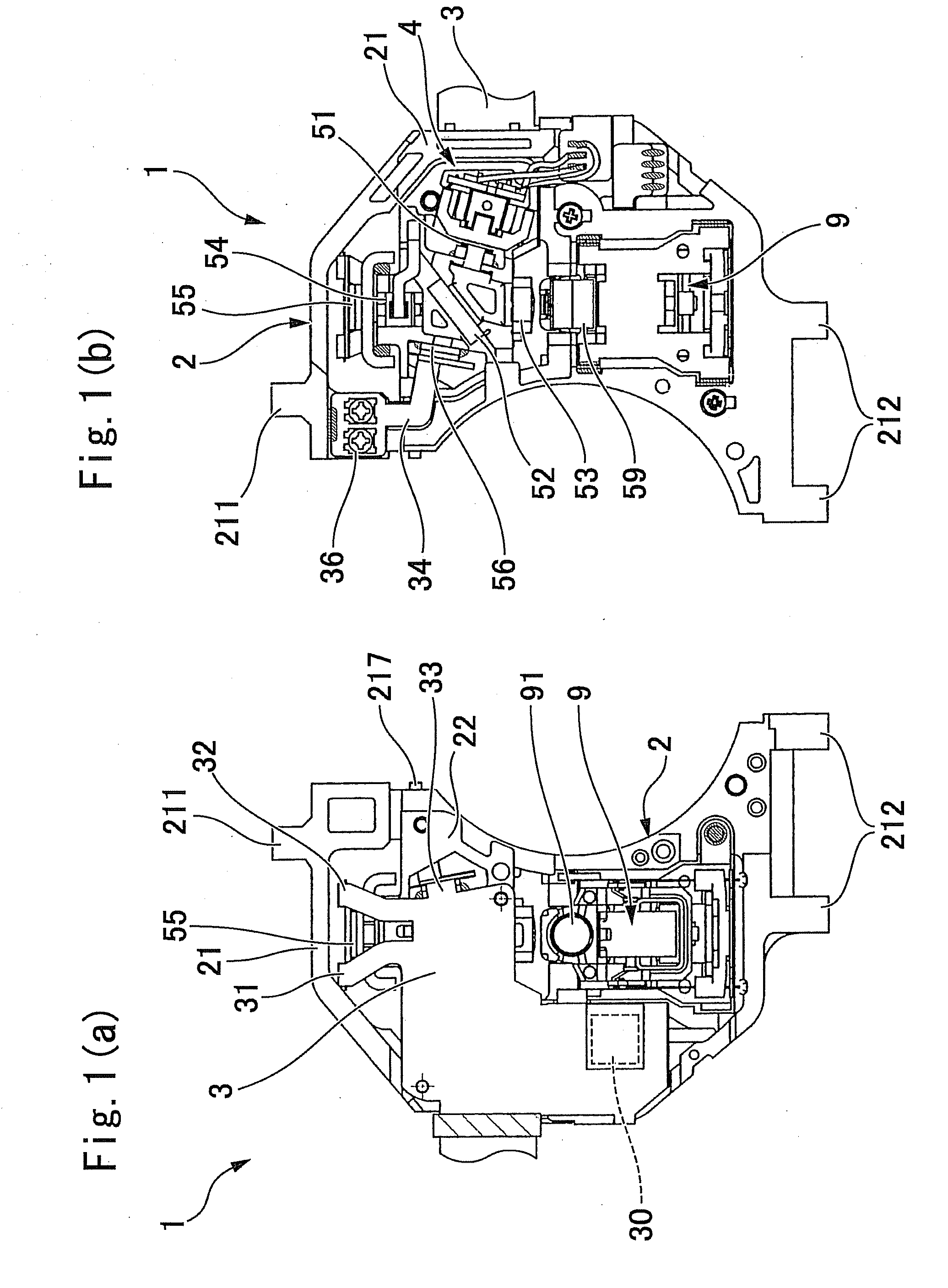
[0018]FIG. 1(a) is a plan view showing an optical head device in accordance with an embodiment of the present invention in a state that an upper cover, an under cover and an actuator cover are detached, and FIG. 1(b) is its bottom view.

[0019]As shown in FIGS. 1(a) and 1(b), in an optical head device 1 to which the present invention is applied, both respective ends of a device frame 2 are formed with a first bearing part 211 and a second bearing part 212 which engage with a guide shaft and a feed screw shaft (not shown) of a disk drive device and the optical head device 1 is driven in a radial direction of an optical disk. An one side face of the device frame 2 is recessed in a ...


PUM


Abstract

An optical head device may include a twin laser light source which is integrally provided with a first laser beam emitting element and a second laser beam emitting element, a light receiving element, and an optical system including an objective lens for converging a laser beam on an optical recording medium. The optical system is provided with a detection lens structured of a toric lens. The toric lens applies an astigmatic difference caused by a toric face to the one of the return light beams, and the toric lens applies the other of the return light beams an astigmatic difference caused by a toric face and astigmatism composed of astigmatism and curvature of image field caused by passing off-axis position to coincide a focusing position of the first laser beam with that of the second laser beam.

Description

CROSS REFERENCE TO RELATED APPLICATION[0001]The present invention claims priority under 35 U.S.C. §119 to Japanese Application No. 2006-247273 filed Sep. 12, 2006, which is incorporated herein by reference.FIELD OF THE INVENTION[0002]An embodiment of the present invention may relate to an optical head device which includes a twin laser light source provided with two laser beam emitting elements which emit laser beams with different wavelengths.BACKGROUND OF THE INVENTION[0003]An optical head device which is capable of reproducing and recording information from and in different types of an optical recording medium (optical disk) such as a CD and a DVD is, for example, structured such that a twin laser light source is used which is provided with a first laser beam emitting element and a second laser beam emitting element which emit laser beams with different wavelengths. When the twin laser light source is used, two laser beams are passed through an approximately common optical path. ...

Claims


Application Information

Patent Timeline
IPC IPC(8): G01B11/14
CPCG11B7/0909G11B7/1378G11B7/1275
Inventor SASAKI, MASAKI
Owner SANKYO SEIKI MFG CO LTD
Learn More