
Carbon nanotube composite

a carbon nanotube and composite technology, applied in the field of polymer-based composites, can solve the problems of insufficient contact between cnts and adjacent cnts, and the cnt of cnts/polymer composites cannot provide direct, shortest-distance thermal conduction path and/or electrical transmission path

Inactive Publication Date: 2008-03-13
TSINGHUA UNIV +1
View PDF11 Cites 102 Cited by
  • Summary
  • Abstract
  • Description
  • Claims
  • Application Information

AI Technical Summary

Benefits of technology

[0009]In one embodiment, a carbon nanotube / polymer composite is provided. The carbon nanotube / polymer composite includes at least one polymer material layer and at least one carbon nanotube / polymer composite layer. The carbon nanotube / polymer layer includes a polymer material and a plurality of carbon nanotubes (CNTs) embedded in the polymer material. The carbon nanotube / polymer layer includes a top surface and a bottom surface opposite to the top surface. At least one of the top surface and bottom surface contacts the adjacent polymer material layer, and adjacent carbon nanotubes contact each other.

Problems solved by technology

Therefore, CNTs typically do not contact with adjacent CNTs sufficiently to facilitate useful levels of conductivity therebetween.
Thus, each CNT of the CNTs / polymer composites cannot provide a direct, shortest-distance thermal conduction path and / or electrical transmission path from one end / side to the other end / side of the composite.

Method used


Image

  • Carbon nanotube composite
  • Carbon nanotube composite
  • Carbon nanotube composite

Examples


Embodiment Construction

[0019]Reference will now be made to the drawings to describe embodiments of the present composite, in detail.

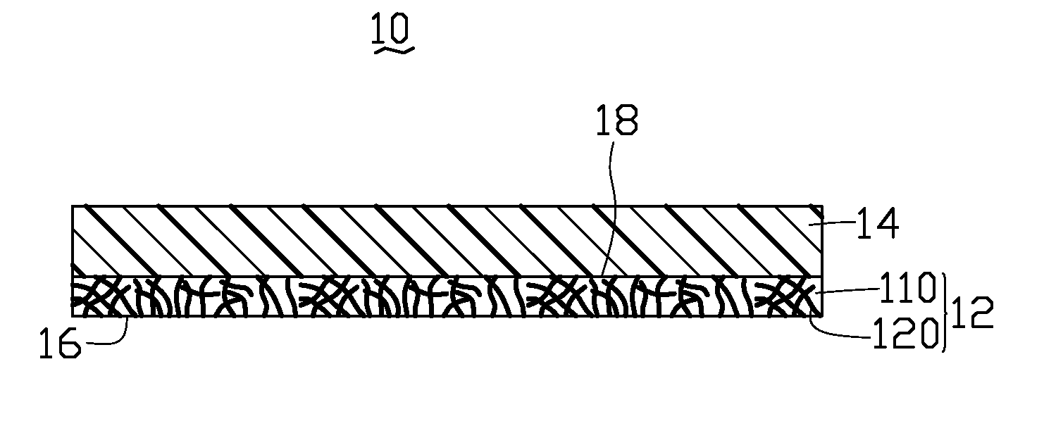
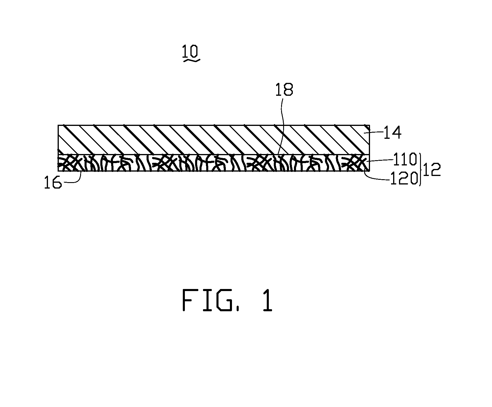
[0020]Referring to FIG. 1, a CNT / polymer composite 10 according to a preferred embodiment is a film structure. The CNT / polymer composite 10 includes a CNT / polymer layer 12 (hereinto also referred simply to as the CNT / polymer layer 12, to avoid confusion with the overall CNT / polymer composite 10) and a polymer material layer 14. The CNT / polymer layer 12 includes a polymer material 110 and a number of CNTs 120 embedded therein. The CNT / polymer layer 12 includes a top surface 18 and a bottom surface 16 opposite thereto. The polymer material layer 14 attaches directly (e.g., via polymer / polymer bond) to the top surface 18 of the CNT / polymer layer 12.

[0021]The polymer material 110 of the CNT / polymer layer 12 and the polymer material of the polymer material layer 14 are, advantageously, selected from the group consisting of polymethyl methacrylate, polyethyl acrylate, polybutyl acr...


PUM

PropertyMeasurementUnit
Lengthaaaaaaaaaa
Lengthaaaaaaaaaa
Thicknessaaaaaaaaaa

Abstract

A carbon nanotube / polymer composite is described. The carbon nanotube / polymer composite includes at least one polymer material layer and at least one carbon nanotube / polymer composite layer. The carbon nanotube / polymer layer includes a polymer material and a plurality of carbon nanotubes embedded in the polymer material, wherein the carbon nanotube / polymer layer includes a top surface and a bottom surface opposite to the top surface, at least one of the top surface and bottom surface contacts with the adjacent polymer material layer, and the carbon nanotubes respectively contact at least one respective adjacent carbon nanotube to thereby yield a network of contacting carbon nanotubes.

Description

RELATED APPLICATIONS[0001]This application is related to a commonly-assigned, co-pending application: U.S. patent application Ser. No. ______, entitled “METHOD OF PREPARING CARBON NANOTUBE / POLYMER COMPOSITE MATERIAL”, filed **** (Atty. Docket No. US11270). The disclosure of the above-identified application is incorporated herein by reference.BACKGROUND[0002]1. Field of the Invention[0003]The invention relates to polymer-based composites and, particularly, to a carbon nanotube / polymer composite.[0004]2. Discussion of Related Art[0005]Carbon nanotubes (also herein referred to as CNTs) were first observed and reported in an article by Iijima in 1991 (Nature, Vol. 354, Nov. 7, 1991, pp. 56-58). CNTs are tube-shaped structures composed of graphite. CNTs have a high Young's modulus, high thermal conductivity, and high electrical conductivity. Due to these and the other properties, it has been suggested that CNTs can play an important role in fields such as microelectronics, material scien...

Claims


Application Information

Patent Timeline
IPC IPC(8): B32B9/00
CPCB32B27/08Y10T428/265Y10T428/30
Inventor SONG, PENG-CHENGZHANG, QIU-CENLIU, CHANG-HONGFAN, SHOU-SHAN
Owner TSINGHUA UNIV
Learn More