Straw Chopper

Inactive Publication Date: 2008-03-13
LAMONT JOHN S
View PDF15 Cites 14 Cited by
  • Summary
  • Abstract
  • Description
  • Claims
  • Application Information

AI Technical Summary

Benefits of technology

[0026]A chute at the outlet of the chopping chamber may also extends at an upward

Problems solved by technology

In heavier soils, for example clay type soils, known straw chopper attachments for combines and the like are generally known to not chop the straw finely enough to be effectively incorporated back into the soil by subsequent agricultural operations.
The straw then interferes with subsequent seeding operations when replanting a new crop, and must be removed or burned.
The configuration o

Method used


Image

  • Straw Chopper
  • Straw Chopper
  • Straw Chopper

Examples


Embodiment Construction

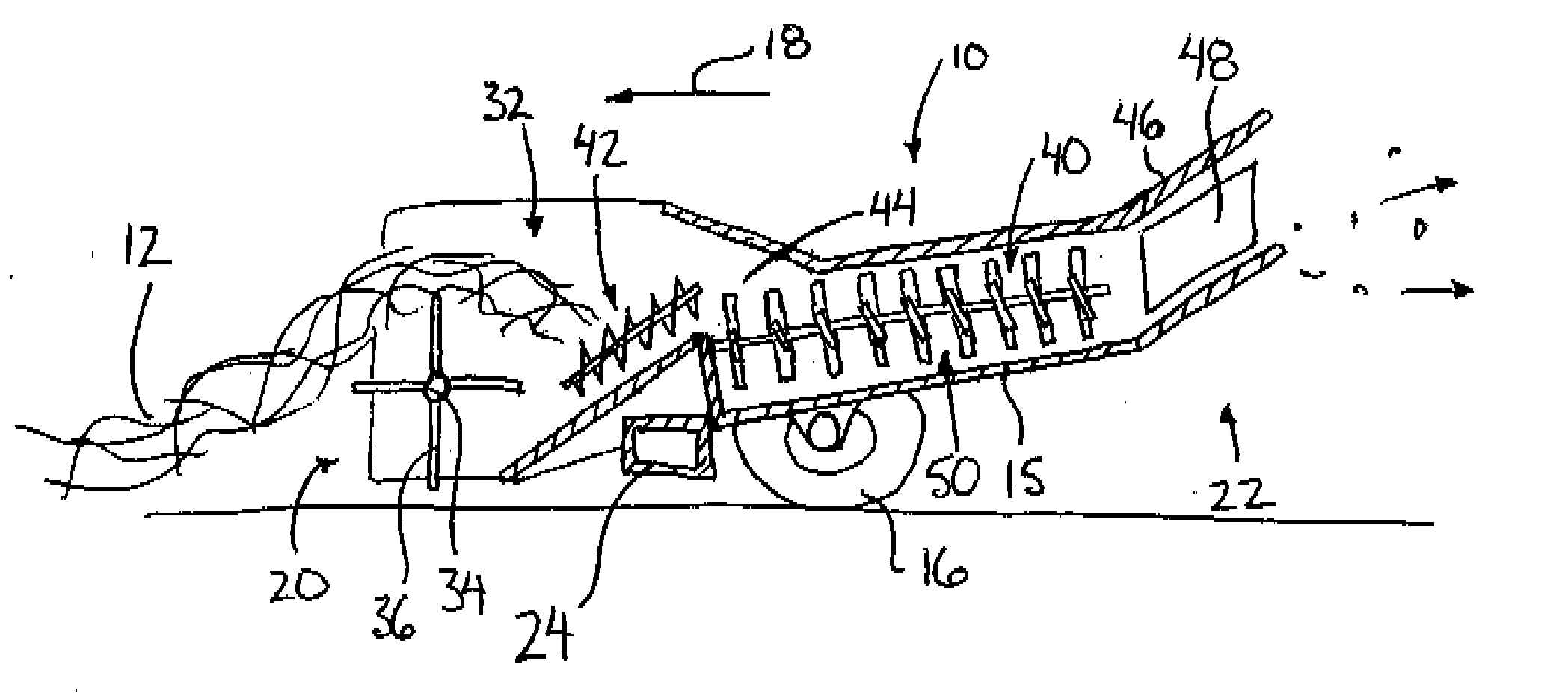
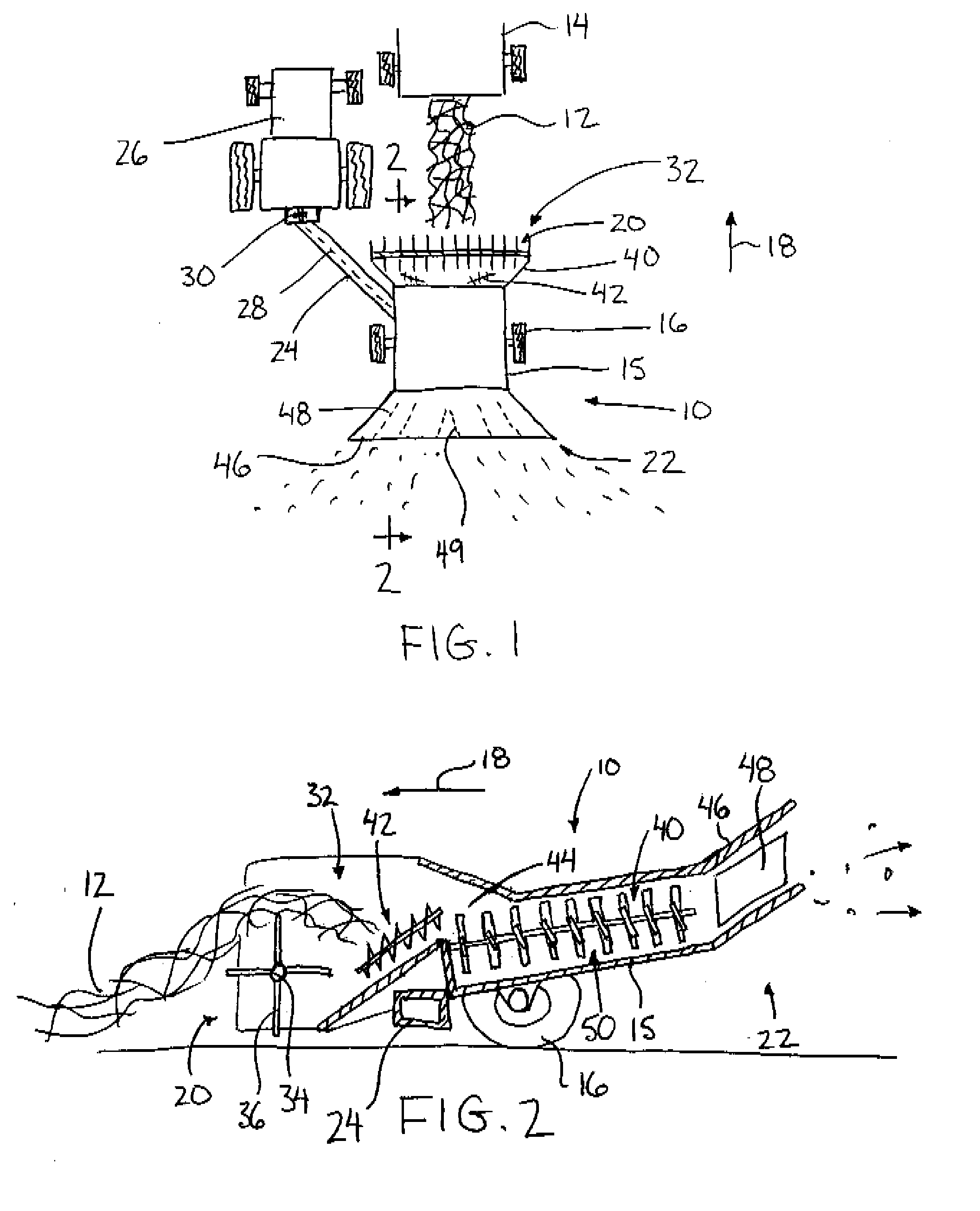
[0034]Referring to the accompanying figures there is illustrated a straw chopper generally indicated by reference numeral 10. The chopper 10 is particularly useful for collecting straw from a windrow 12 of cut straw along the ground, however in some embodiments the chopper may be arranged to collect cut straw directly from the discharge of a combine 14. Whether the chopper collects the straw from a windrow 12 on the ground which has been previously discharged from a combine or collects the straw directly from the combine, in either instance the straw is collected, more finely chopped and then spread back onto the ground for subsequent incorporation into the soil, thus assisting the soil in retaining moisture and returning nutrients to the soil.

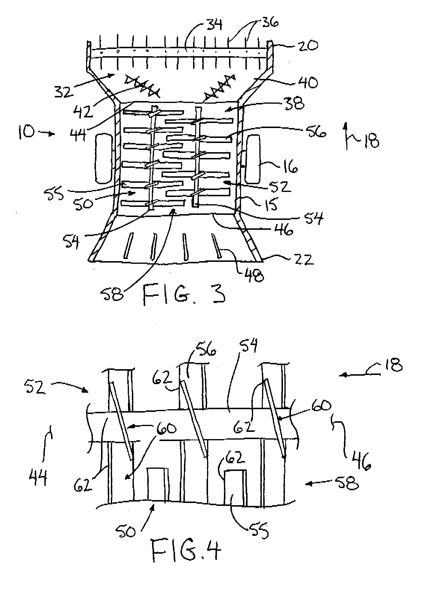
[0035]The chopper 10 includes a frame 15 supported on wheels 16 for rolling movement in a forward working direction 18 of the chopper. The chopper is arranged to collect straw from the windrow on the ground at a front end 20 of the chopper whi...


PUM


Abstract

A straw chopper includes a pair of shafts supported in a chopping chamber for rotation about respective longitudinal axes extending generally in a forward working direction of the chopper. Chopping blades are supported on each shaft, offset in a direction of the longitudinal axes in relation to the chopping blades of the other shaft so that the shafts can be positioned with a sweep area of the blades overlapping one another. The shafts are rotated in a common direction of rotation such that the blades of one of the shafts are displaced in an opposite direction to the blades of the other one of the shafts at the overlap of the sweep areas. Each chopping blade includes an impeller surface sloped forwardly into a direction of rotation so as to generate a rearward thrust of air in the chopping chamber in the longitudinal direction of the axes from the inlet to the outlet of the chamber as the shafts are rotated.

Description

[0001]This application claims foreign priority benefits from Canadian Patent Application 2,559,484 filed Sep. 11, 2006.FIELD OF THE INVENTION[0002]The present invention relates to a straw chopper for chopping straw into finer particles prior to spreading onto the ground for subsequent incorporation into the ground.BACKGROUND[0003]When harvesting grains and the like, it is a known practice to chop up the straw portion for redistribution over the ground. Redistributing the chopped up straw on the ground assists in maintaining moisture in the ground and also acts to return some nutrients back to the ground. In light soils, disc units are generally known to be effective to incorporate the straw into the soil and further break-up the straw to aid in its incorporation back into the soil. In heavier soils, for example clay type soils, known straw chopper attachments for combines and the like are generally known to not chop the straw finely enough to be effectively incorporated back into th...

Claims


Application Information

Patent Timeline
IPC IPC(8): A01F12/40
CPCA01F29/025Y10S241/605
Inventor LAMONT, JOHN S.
Owner LAMONT JOHN S
Why Eureka
Try Eureka