Sound Encoding Device And Sound Encoding Method

a technology of encoding device and encoding method, which is applied in the direction of speech analysis, code conversion, instruments, etc., can solve the problem that smooth conversation cannot be performed, and achieve the effect of reducing delay and alleviating distortion between frames

Active Publication Date: 2008-03-13
OPTIS WIRELESS TECH LLC
View PDF20 Cites 48 Cited by
  • Summary
  • Abstract
  • Description
  • Claims
  • Application Information

AI Technical Summary

Benefits of technology

[0013] According to the present invention, it is possible to suppress the amount of delay low and alleviate the distortion between frames.

Problems solved by technology

If this delay increases in bidirectional communication, it takes time for a response from a terminal to arrive at the other terminal, and therefore smooth conversation cannot be performed.

Method used


Image

  • Sound Encoding Device And Sound Encoding Method
  • Sound Encoding Device And Sound Encoding Method
  • Sound Encoding Device And Sound Encoding Method

Examples


embodiment 1

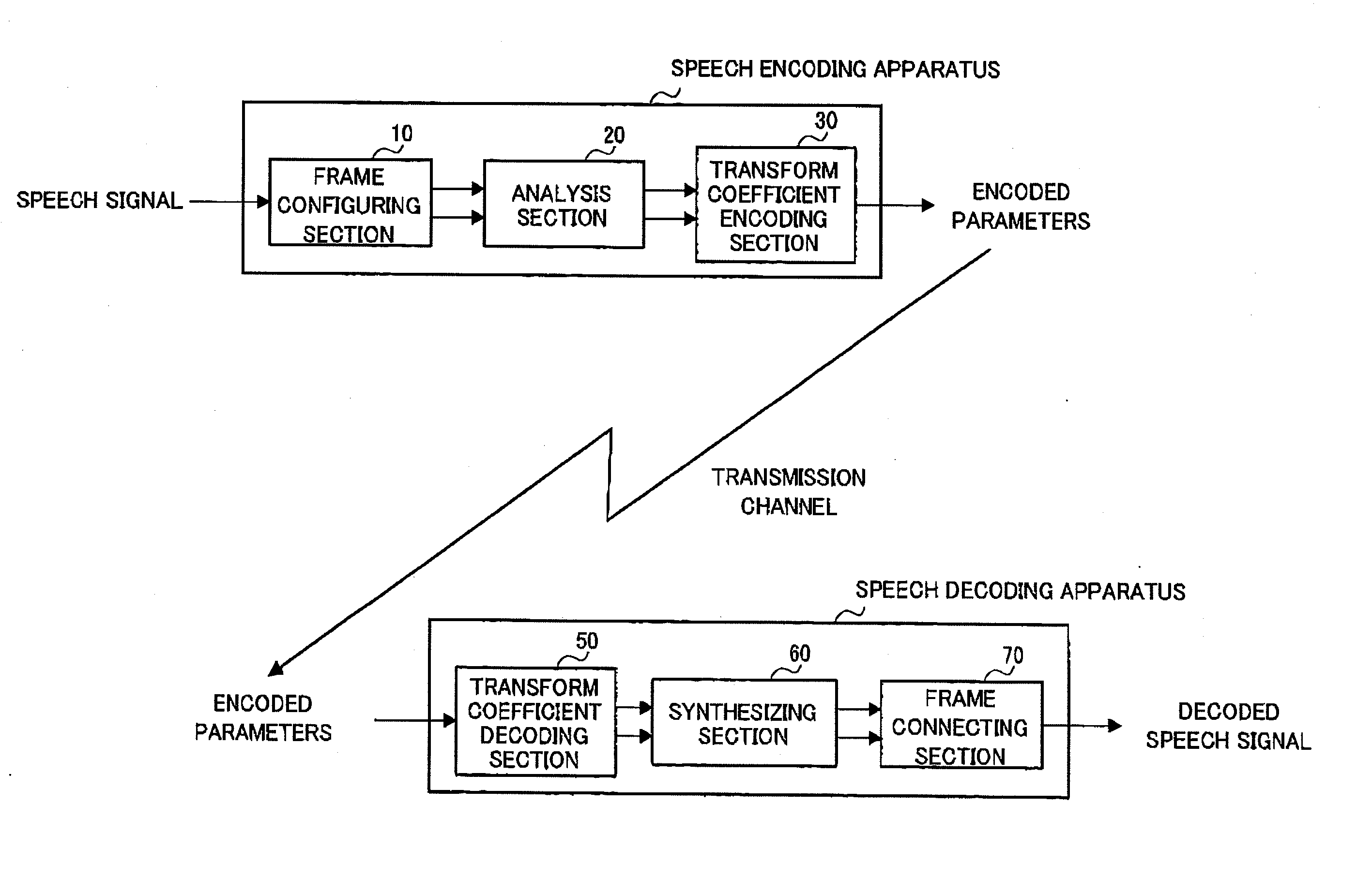
[0029] The configurations of a speech encoding apparatus and a speech decoding apparatus according to Embodiment 1 of the present invention are shown in FIG. 3. As shown in the drawing, the speech encoding apparatus includes frame configuring section 10, analysis section 20 and transform coefficient encoding section 30. The speech decoding apparatus includes transform coefficient decoding section 50, synthesizing section 60 and frame connecting section 70.

[0030] In the speech encoding apparatus, frame configuring section 10 forms a time-domain speech signal to be inputted, into frames. Analysis section 20 transforms the time-domain speech signal broken into frames, into a frequency-domain signal by MDCT analysis. Transform coefficient encoding section 30 encodes transform coefficients obtained by analysis section 20 and outputs encoded parameters. The encoded parameters are transmitted to the speech decoding apparatus through a transmission channel.

[0031] In the speech decoding ap...

embodiment 2

[0050] When a speech signal to be inputted to a speech encoding apparatus is a beginning portion of a word or a transition portion where characteristics rapidly change, time resolution is required rather than frequency resolution. For such a speech signal, speech quality is improved by analyzing all analysis frames using short analysis frames.

[0051] In view of this, in the present embodiment, MDCT analysis is performed on each frame by switching between (1) a mode (long-short combined analysis mode) in which the analysis is performed by a combination of long analysis and short analysis and (2) a mode (all-short analysis mode) in which short analysis is repeatedly performed a plurality of times, according to the characteristics of the input speech signal. An example of analysis / synthesis windows to be used for each frame in the all-short analysis mode is shown in FIG. 12. The long-short combined analysis mode is the same as that described in Embodiment 1.

[0052] The configuration of...


PUM


Abstract

A sound encoding device enabling the amount of delay to be kept small and the distortion between frames to be mitigated. In the sound encoding device, a window multiplication part (211) of a long analysis section (21) multiplies a long analysis frame signal of analysis length M1 by an analysis window, the resultant signal multiplied by the analysis window is outputted to an MDCT section (212), and the MDCT section (212) performs MDCT of the input signal to obtain the transform coefficients of the long analysis frame and outputs it to a transform coefficient encoding section (30). The window multiplication part (221) of a short analysis section (22) multiplies a short analysis frame signal of analysis length M2 (M2<M1) by an analysis window and the resultant signal multiplied by the analysis window is outputted to the MDCT section (222). The MDCT section (222) performs MDCT of the input signal to obtain the transform coefficients of the short analysis frame and outputs it to the transform coefficient encoding section (30). A transform coefficient encoding section (30) encodes these transform coefficients and outputs them.

Description

TECHNICAL FIELD [0001] The present invention relates to a speech encoding apparatus and a speech encoding method. BACKGROUND ART [0002] In speech encoding, transform encoding whereby a time signal is transformed into a frequency domain and transform coefficients are encoded, can efficiently eliminate redundancy contained in the time domain signal. In addition, in the transform encoding, by utilizing perceptual characteristics represented in the frequency domain, it is possible to implement encoding in which quantization distortion is difficult to be perceived even at a low bit rate. [0003] In transform encoding for the recent years, a transform technique called lapped orthogonal transform (LOT) is often used. In LOT, transform is performed based on an orthogonal function taking into consideration not only the orthogonal components within a block but also the orthogonal components between adjacent blocks. Typical techniques of such transform include MDCT (Modified Discrete Cosine Tra...

Claims


Application Information

Patent Timeline
Patent Type & Authority Applications(United States)
IPC IPC(8): G10L19/02G10L19/022G10L25/45
CPCG10L19/022G10L19/0212G10L19/00H03M7/30
Inventor OSHIKIRI, MASAHIRO
Owner OPTIS WIRELESS TECH LLC
Why Eureka
Try Eureka