Logical volume management method and logical volume management program

a logical volume and management method technology, applied in the direction of instruments, computing, electric digital data processing, etc., can solve the problems of wasting the possible count of data rewriting of flash memory drives, the length of logical volume on flash memory drives, and the limitation of flash memory data rewriting coun

Inactive Publication Date: 2008-03-13
HITACHI LTD
View PDF5 Cites 65 Cited by
  • Summary
  • Abstract
  • Description
  • Claims
  • Application Information

AI Technical Summary

Benefits of technology

[0015]In still another aspect of the present invention, there is provided a logical volume management method for a computer system comprising: at least one host computer; and at least one storage system having at least one physical storage device-chip as storage medium with a complete data erasing function, and providing at least one logical volume to the host computer, the host computer and the storage system being connected with each other through a network, the method comprising steps of: allowing the host computer: to allocate a logical volume requested in a logical volume creation request to unallocated physical storage device-chip if the host computer receives the logical volume creation request, and if a storage capacity of the logical volume requested in the logical volume creation request is equal to or smaller than a total storage capacity of the unallocated physical storage device-chip.
[0016]In still another aspect of the present invention, there is provided a logical volume management method for a computer system comprising: at least one host computer; and at least one storage system having at least one physical storage device-chip as storage medium with a complete data erasing function, and providing at least one logical volume to the host computer, the host computer and the storage system being connected with each other through a network, the method comprising steps of: allowing the host computer: to allocate an erasing group requested in an erasing group formation request with a retention period for forming an erasing group that can be erased at a time on an expiration of the data retention period to unallocated physical storage device-chip if the host computer receives the erasing group formation request with a retention period, and if a storage capacity of the erasing group requested in the erasing group formation request with a retention period is equal to or smaller than a total storage capacity of the unallocated physical storage device-chip.
[0017]In still another aspect of the present invention, there is provided a logical volume management computer-readable media for a computer system comprising: at least one host computer; and at least one storage system having at least one physical storage device-chip as storage medium with a complete data erasing function and providing at least one logical volume to the host computer, the host computer and the storage system being connected with each other through a network, the computer-readable media having instructions executable by the host computer or a computer of the storage system for performing steps of: receiving a logical volume creation request; and allocating a logical volume requested in the logical volume creation request to unallocated physical storage device-chip if a storage capacity of the logical volume requested in the logical volume creation request is equal to or smaller than a total storage capacity of the unallocated physical storage device-chip.
[0018]In still another aspect of the present invention, there is provided a logical volume management computer-readable media for a computer system comprising: at least one host computer; and at least one storage system having at least one physical storage device-chip as storage medium with a complete data erasing function and providing at least one logical volume to the host computer, the host computer and the storage system being connected with each other through a network, the computer-readable media having instructions executable by the host computer or a computer of the storage system for performing steps of: receiving an erasing group formation request with a retention period for forming an erasing group that can be erased at a time on an expiration of the data retention period; and allocating the erasing group requested in the erasing group formation request with a retention period to unallocated physical storage device-chip if a storage capacity of the erasing group requested in the erasing group formation request with a retention period is equal to or smaller than a total storage capacity of the unallocated physical storage device-chip.
[0019]In still another aspect of the present invention, there is provided a computer system comprising: at least one host computer; and at least one storage system providing at least one logical volume to the host computer, the host computer and the storage system being connected with each other through a network, wherein the storage system has at least one physical storage device-chip as storage medium with a complete data erasing function, and the host computer allocates a logical volume requested in a logical volume creation request to unallocated physical storage device-chip if the host computer receives the logical volume creation request, and if a storage capacity of the logical volume requested in the logical volume creation request is equal to or smaller than a total storage capacity of the unallocated physical storage device-chip.
[0020]In still another aspect of the present invention, there is provided a computer system comprising: at least one host computer; and at least one storage system providing at least one logical volume to the host computer, the host computer and the storage system being connected with each other through a network, wherein the storage system has at least one physical storage device-chip as storage medium with a complete data erasing function, and the host computer allocates an erasing group requested in an erasing group formation request with a retention period for forming an erasing group that can be erased at a time on an expiration of the data retention period to unallocated physical storage device-chip if the host computer receives the erasing group formation request with a retention period, and if a storage capacity of the erasing group requested in the erasing group formation request with a retention period is equal to or smaller than a total storage capacity of the unallocated physical storage device-chip.

Problems solved by technology

Therefore, when overwriting of data is repeated several times, there arises a problem that a time period for performing complete erasing of logical volume on the flash memory drive becomes longer than a time period for performing complete erasing of logical volume on the conventional hard disk.
Further, a flash memory has a limitation in data rewrite count.
When overwriting of data is repeated several times and complete erasing of logical volume on a flash memory drive is repeatedly performed, there arises a problem that a possible count of data rewriting of flash memory drive is wasted.

Method used


Image

  • Logical volume management method and logical volume management program
  • Logical volume management method and logical volume management program
  • Logical volume management method and logical volume management program

Examples


embodiment 1

[0051]A configuration of a computer system according to Embodiment 1 of the present invention will be described below.

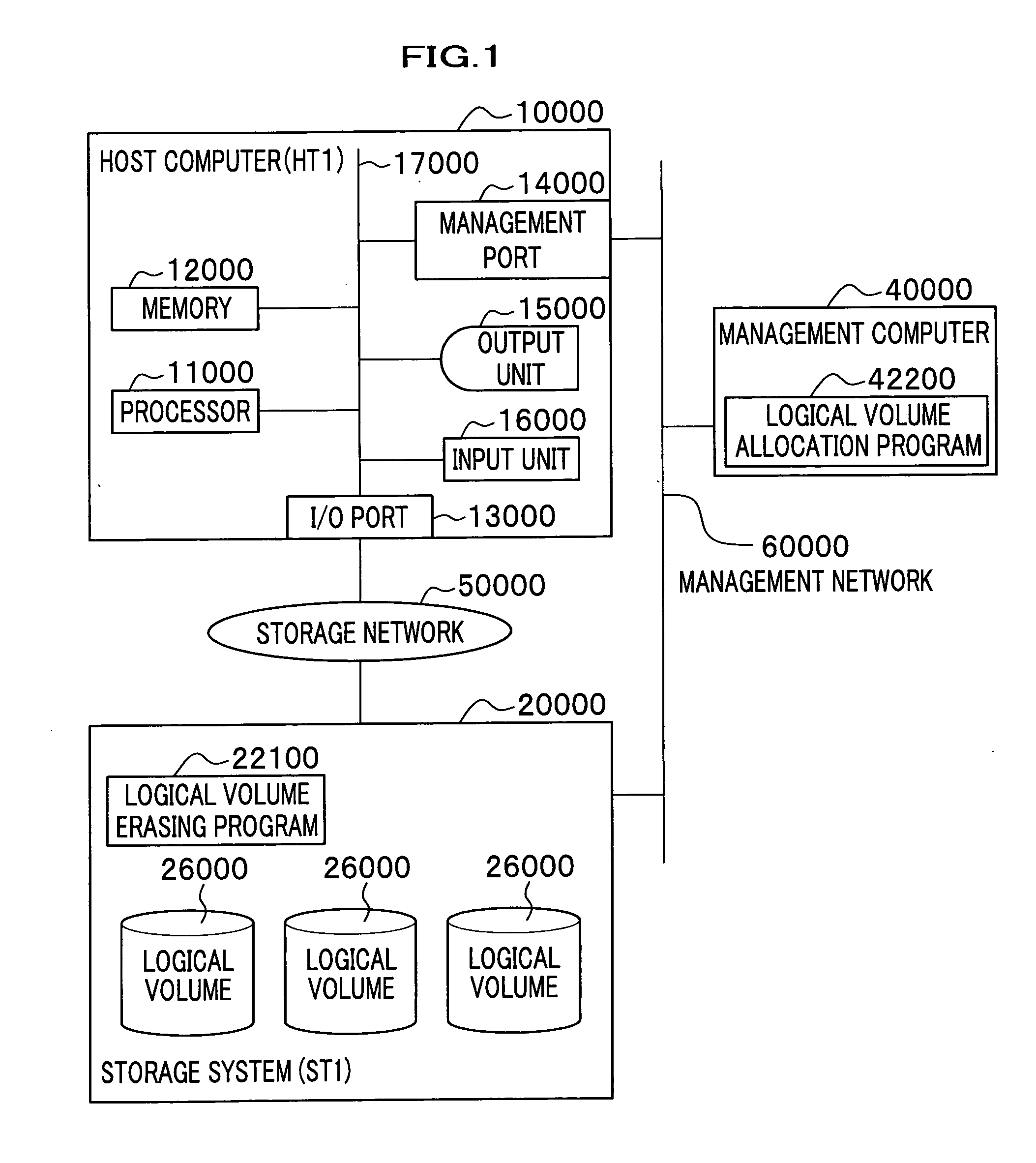
[0052]FIG. 1 is a block diagram showing a configuration of a computer system according to Embodiment 1. One or more host computers 10000 and one or more storage systems 20000 are connected with each other through a storage network 50000.

[0053]The host computer 10000 includes: a processor 11000; a memory 12000; one or more I / O ports 13000 for connecting with the storage network 50000; a management port 14000 for connecting with a management network 60000; an output unit 15000, such as display device, for outputting processing results; and an input unit 16000, such as keyboard and mouse. These are connected with one another through an internal bus 17000. The memory 12000 stores an OS (not shown) and an application (not shown) for processing associated with data access to the storage system 20000. These programs are read from storage media (not shown), such as hard disk...

embodiment 2

[0092]A configuration of a computer system according to Embodiment 2 of the present invention will be described with reference to FIGS. 14-17. It should be noted that, in the description of the computer system in Embodiment 2, only the differences from Embodiment 1 will be explained. In the configuration of the computer system in Embodiment 2, the same components as in Embodiment 1 are designated with the same reference characters, and a duplicate description is omitted. The configuration of the flash memory drive in Embodiment 2 is the same as that of the flash memory drive in Embodiment 1, and a duplicate description is omitted.

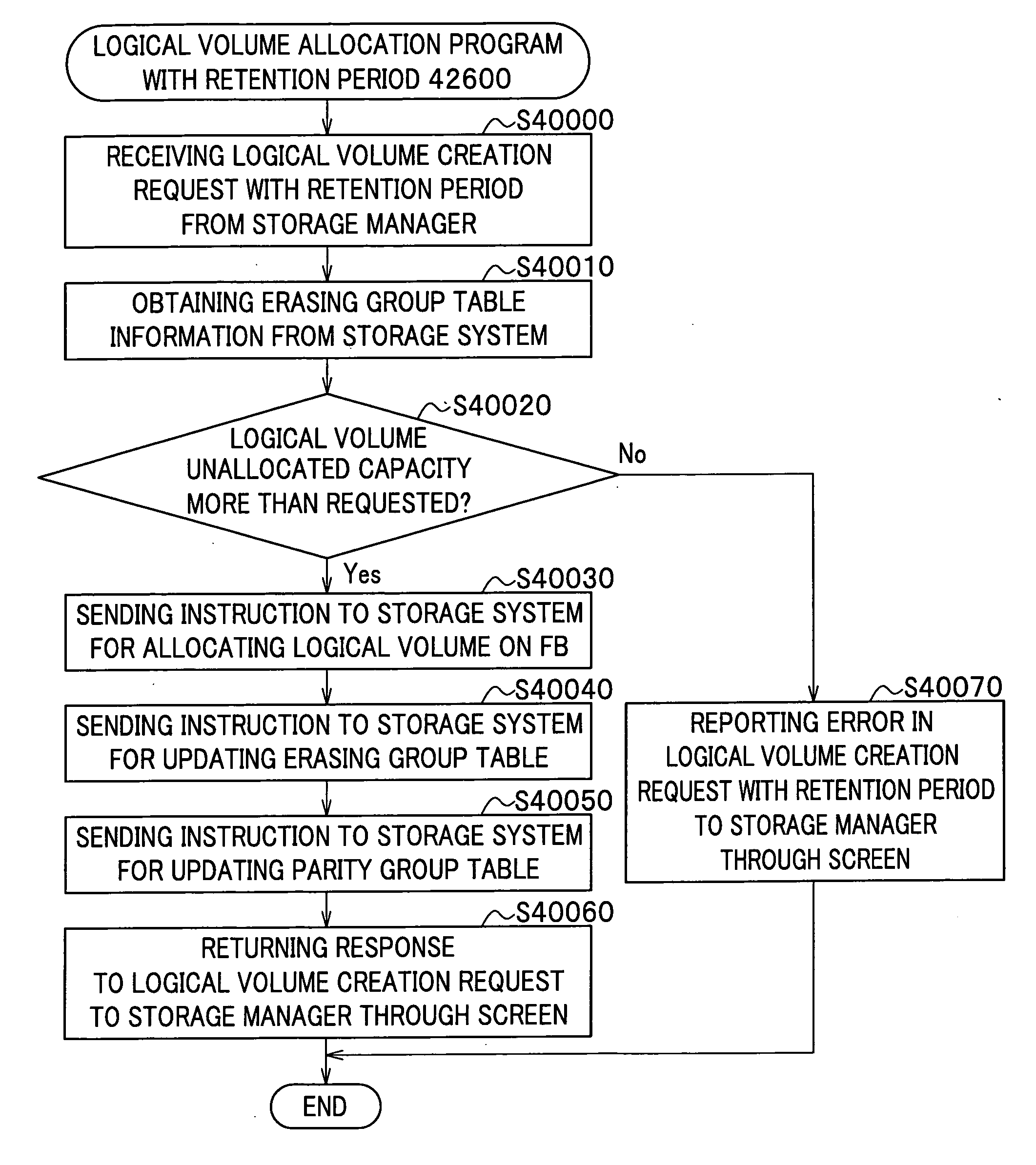
[0093]FIG. 14 is a block diagram showing a configuration of a computer system according to Embodiment 2. Embodiment 2 shown in FIG. 14 is different from Embodiment 1 shown in FIG. 1 in that, instead of the logical volume allocation program 42200, an erasing group formation program 42500 and a logical volume allocation program with a limited retention period...


PUM


Abstract

There is provided a logical volume management method for storage system. When a logical volume is created on a flash memory drive, a management computer allocates logical volume while flash memory chip border of flash memory drive is taken into account. Specifically, a table for managing a correlation between each parity group and the flash memory chip of the flash memory drive is obtained and the logical volume is allocated in such a manner that a flash memory chip is not shared by a plurality of logical volumes. When complete erasing of logical volume data is performed, the management computer specifies a flash memory chip on which complete data erasing is to be performed, and the storage system completely erases data exclusively on the chip of interest with a use of a function of completely erasing data at a time by chip unit of the flash memory chip (chip erasing).

Description

CROSS-REFERENCE TO RELATED APPLICATIONS[0001]This application claims the foreign priority benefit under Title 35, United States Code, section 119 (a)-(d), of Japanese Patent Application No. 2006-246475, filed on Sep. 12, 2006 in the Japan Patent Office, the disclosure of which is herein incorporated by reference in its entirety.BACKGROUND OF THE INVENTION[0002]1. Field of the Invention[0003]The present invention relates to a logical volume management method and a logical volume management program of a storage system used for a computer system, and a computer system.[0004]2. Description of the Related Art[0005]A storage system generally includes randomly accessible nonvolatile storage media, such as magnetic disk and optical disk. The most common storage system at present has many compact-size disk drives. On the other hand, as semiconductor technology advances, there has been developed a nonvolatile semiconductor memory that can retain data even after turning off a power supply and ...

Claims


Application Information

Patent Timeline
Patent Type & Authority Applications(United States)
IPC IPC(8): G06F12/00G06F21/60G06F21/80
CPCG06F3/061G06F3/0616G06F3/0688G06F3/0665G06F3/0679G06F3/064
Inventor NASU, HIROSHIYAMAMOTO, MASAYUKITAGUCHI, YUICHI
Owner HITACHI LTD
Why Eureka
Try Eureka