

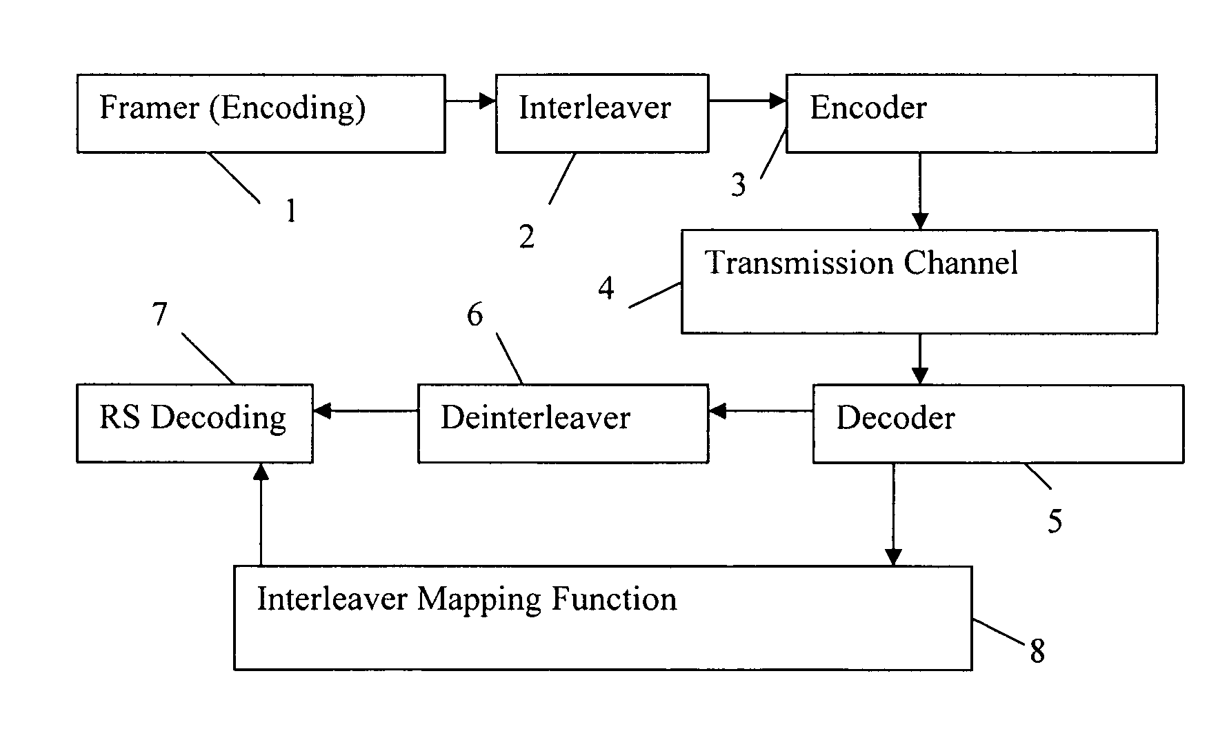
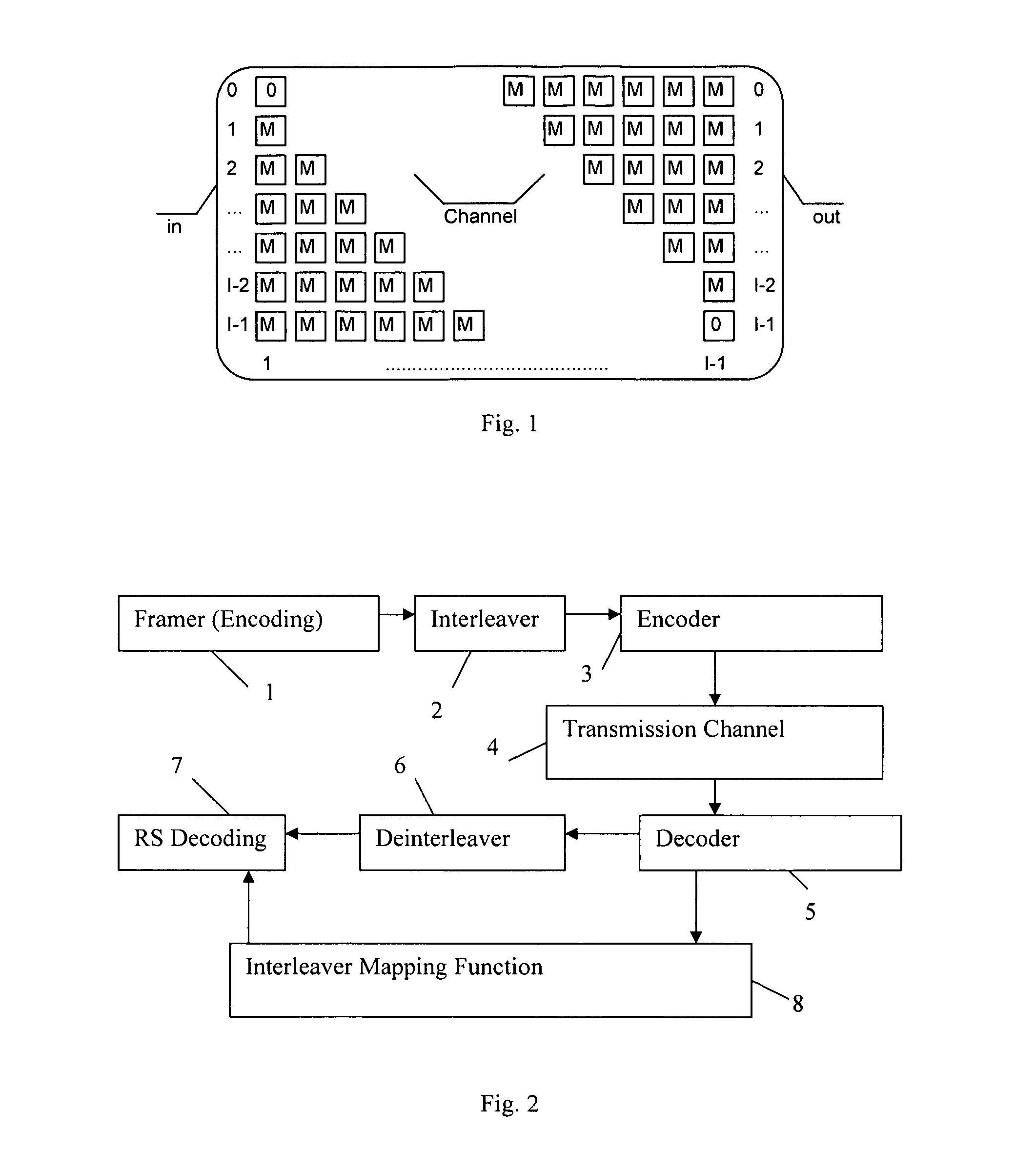
Decoder system for data encoded with interleaving and redundancy coding
a data encoder and data technology, applied in the field of data extraction systems, can solve the problems of the total number of errors which can be present in the received data string, and achieve the effect of increasing the data transmission rate along a given data transmission path
- Summary
- Abstract
- Description
- Claims
- Application Information
AI Technical Summary
Benefits of technology
Problems solved by technology
Method used
Image

Examples
example 1
M=1, D=5, MI−1=3
[0143]Suppose that the third DMT symbol is found to be corrupt (step 1). Consider arranging the 16 bytes of this symbol in the arrangement shown in FIG. 8. In this figure each ellipse indicates one of the bytes of the corrupt symbol. The first I bytes (i.e. the first 4 bytes) are respectively the ellipses in the first column of FIG. 8 (in the vertically descending order). The next I bytes are the ellipses in the second column of the FIG. 8.
[0144]The numerical values shown in each of the ellipses show the locations of the bytes in the de-interleaved data. These locations are 32292623363330274037343144413835. This data is obtained by direct application of Eqn. (4), for example, but the identifier unit 8 does not have the computing capacity to perform this calculation for general values of the parameters of the embodiment. Instead, the function of the identifier unit 8 is to obtain this data using the following method.
[0145]From first principles (e.g. Eqn. (4)), the loc...
example 2
M=2, D=9, MI−1=7
[0169]In this case, the locations are as shown in FIG. 9. By direct application of Eqn. 4, the locations of the corrupted data of the third DMT Symbol are 32251811362922154033261944373023. The identifier unit 8 performs the method of FIG. 6, to output the locations in sequence, as 11151819222325262930323336374044.
[0170]The method finds that the end of a codeword has been reached at locations 15 and 23. That is, it finds that this corrupt symbol includes bytes 11 and 15 of the third codeword, and bytes 18, 19, 22, 23 of the fourth codeword. These two codewords can now be processed by the unit 7. Later codewords can only be processed when the next DMT symbol arrives.
[0171]Based on step 4 and procedure described in FIG. 7, deinterleaved byte sequence (11151819222325262930323336374044) is generated.
[0172]To explain this, Current byte is set to =32−I*(MI−1)=32−21=11 and n=0, j=0, k=0;
[0173]1. M=2 and j=0 Next Byte in sequence=11+(4−0)=15, n=0, j=1, k=0;
[0174]2. Next Byte ...
example 3
M=3, D=13, MI−1=11
[0183]In this case, the locations are as shown in FIG. 10. By direct application of Eqn. 4, the locations of the corrupted data of the third DMT Symbol are 322110 X 3625143402918744332211. Here, the value X indicates an invalid byte location, in which the de-interleaver will send a dummy byte. Thus, in step 2, the counter is set to 32-(I−1) (MI−1)=32−11*3=−1, which is an invalid value. In this case step 1 should be repeated, but starting at the location which is at the top of the next location to the right, i.e. location 32+I=36. Thus, in step 2 the counter should be set to 32−11*3=3.
[0184]The identifier unit 8 performs the method of FIGS. 6 and 7, to output the locations in sequence, as X 3710111418212225293233364044. Similarly, this sequence is generated using step 4 and procedure described in FIGS. 6 and 7.
[0185]Method 2
[0186]Given eqn. (1), there will be S codewords available for RS decoding after QT processing of one DMT symbol and there are [M(I−1) / q] remaini...
PUM
 Abstract
Description
Claims
Application Information