Video signal processing circuit

a signal processing and video technology, applied in the field of video signal processing circuits, can solve problems such as serious emi problems, and achieve the effects of reducing the number of signal lines required to transmit image data, high data transmission speed, and easy minimization of display device siz

Inactive Publication Date: 2014-01-16
OPTOMEDIA TECH
View PDF1 Cites 7 Cited by
  • Summary
  • Abstract
  • Description
  • Claims
  • Application Information

AI Technical Summary

Benefits of technology

[0016]The advantage of the present invention lies in that the video signal processing circuit of the present invention utilizes optical signals to achieving high speed data transmission. The number of the signal lines required to transmitting image data is reduced, such that the size of the display device can be easily minimized. Moreover, compared with the cost of the high speed video data transceiver in the art, the costs of the optical transmitters and the optical receivers are lower, so as to reduce the manufacturing cost of related hardware.

Problems solved by technology

Problems, such as signal line arrangement or timing skew among signal lines might result.
Through LVDS, data transmission is performed under fixed frequencies; signal energy is concentrated to some band, which causes serious EMI problems.

Method used


Image

  • Video signal processing circuit
  • Video signal processing circuit
  • Video signal processing circuit

Examples


first embodiment

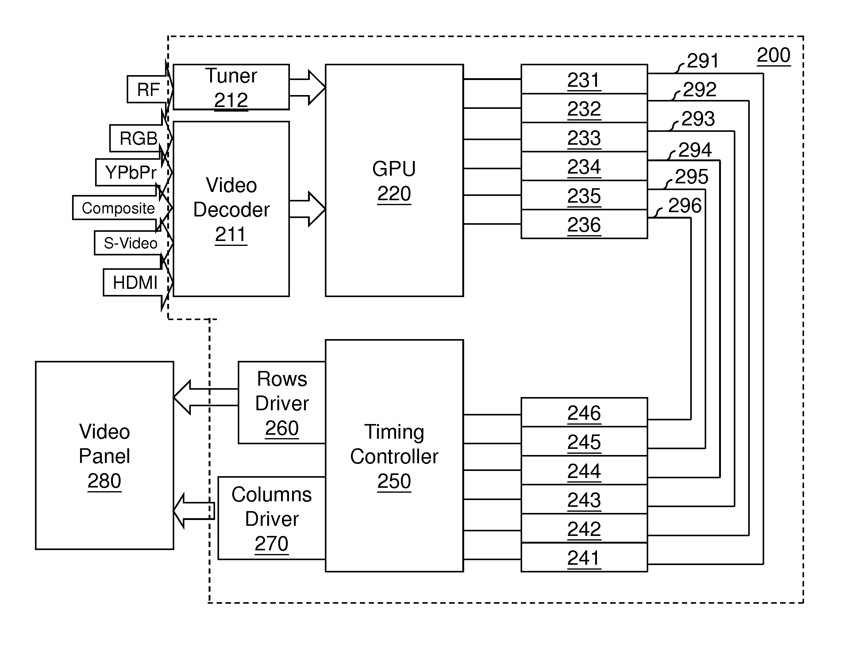
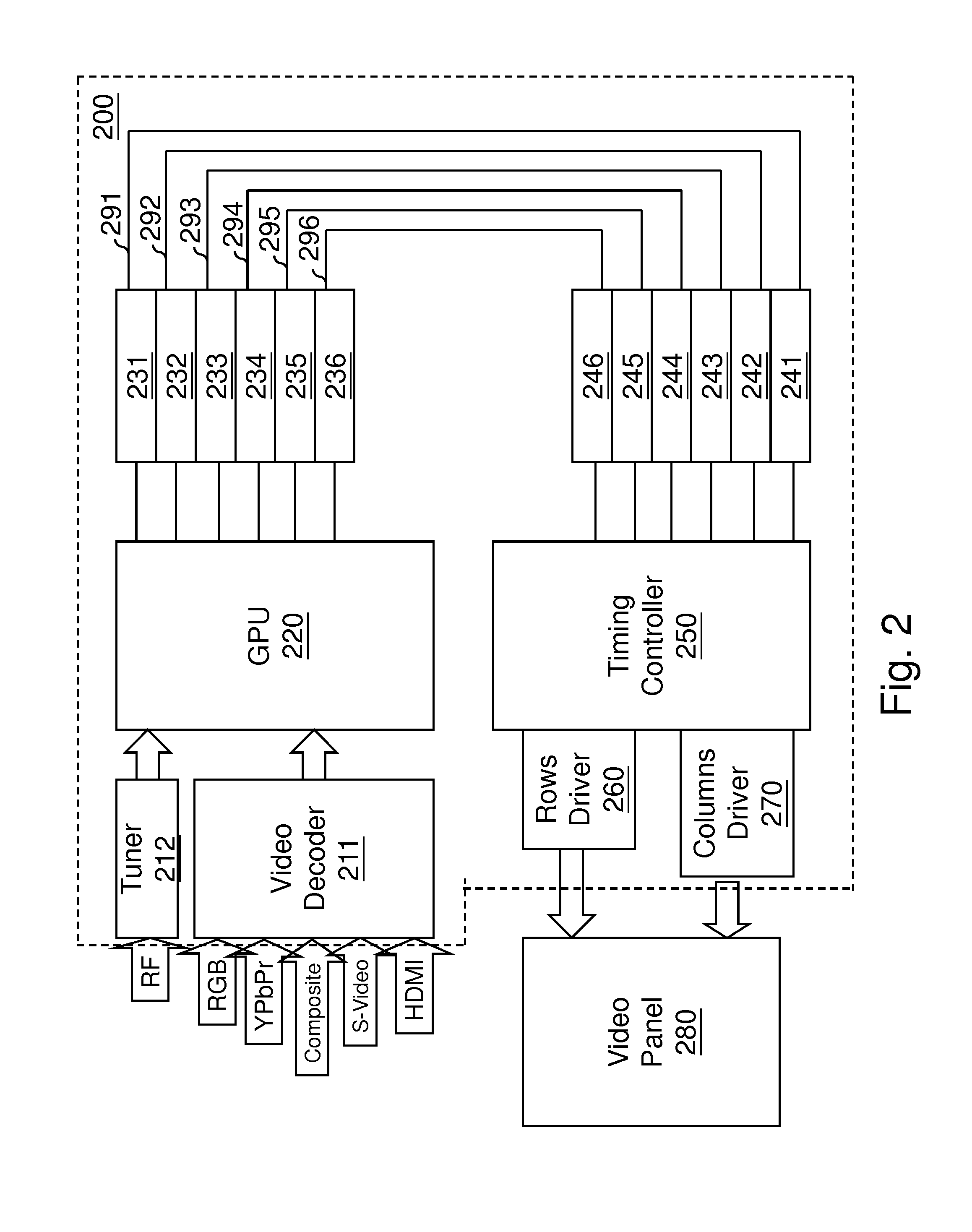
[0024]FIG. 2 is a block diagram of a video signal processing circuit 200 according to the present invention. The video signal processing circuit 200 is used to receive electrical video signals having various standard formats and then transform the electrical video signals into electrical control signals for controlling a display device. The format of the standard video signal includes RGB, YPbPr, Composite, S-Video, HDMI, NTSC, PAL, and the other common used formats. The RGB, YPbPr, Composite, S-Video, and HDMI can be decoded by an image decoder 211, so as to transform those signal formats into one single format and then transmit the transformed signals to a graphics processing unit (GPU) 220. Commercial TV service provider utilizes NTSC or PAL format signals to transmit or broadcast TV signals. The NTSC or PAL format signals is received by a tuner 212 and then transmitted to the GPU 220. It is noted that the image decoder 211 and tuner 212 can be integrated into the GPU 220. Separa...

second embodiment

[0032]FIG. 3 is a block diagram of the video signal processing circuit 300 according to this disclosure. The video signal processing circuit 300 includes a GPU 320 and an optical transmitter 331. The video signal processing circuit 300 is used to receive electrical video signals having various standard formats and then transform the electrical video signals into electrical control signals for controlling a display device. The format of the standard video signal includes RGB, YPbPr, Composite, S-Video, HDMI, NTSC, PAL, and the other common used formats. The RGB, YPbPr, Composite, S-Video, and HDMI can be decoded by an image decoder 311, so as to transform those signal formats into one single format and then transmit the transformed signals to the GPU 320. Commercial TV service provider utilizes NTSC or PAL format signals to transmit or broadcast TV signals. The NTSC or PAL format signals is received by a tuner 312 and then transmitted to the GPU 320. It is noted that the image decode...

third embodiment

[0037]FIG. 4 is a block diagram of the video signal processing circuit 400 according to this disclosure. The optical receiver 441 receives optical control signals transmitted by an optical fiber, and directly recovers the optical control signal into the electrical control signal. The directly recovering or direct recovery in the present invention means a reversal procedure of directly transforming or direct transformation. More precisely, the optical 441 transforms the optical signal status (for example, the wavelength) of each received optical signal into corresponding bit of data of the electrical control signal without other data processing procedure.

[0038]The timing controller 450 electrically couples to the optical receiver 441 and receives the electrical control signal, so as to generate a driving signal to driving a video panel 480 of the display device. For example, in the video signal processing circuit 400, the timing controller 450 directly controls the rows driver 460 an...


PUM


Abstract

A video signal processing circuit includes a graphics processing unit (GPU) and an optical transmitter. The GPU receives an electrical video signal having a standard format, and transforms the electrical video signal into an electrical control signal for controlling a display device. The optical transmitter electrically connects to the GPU for receiving the electrical control signal, so as to transform the electrical control signal into an optical signal and emit the optical signal.

Description

CROSS-REFERENCE TO RELATED APPLICATIONS[0001]This application claims the benefit of the filing date priority of a co-pending U.S. Provisional Application No. 61 / 671,908 filed on Jul. 16, 2012, the disclosure of which is incorporated herein by reference in its entirety.BACKGROUND[0002]1. Field of the Invention[0003]The present invention relates to a video signal processing circuit, and more particularly, to a video signal processing circuit using optical signals to achieving high speed data transmission.[0004]2. Related Art[0005]Regarding to a video panel in the modern mainstream, for example a LCD panel or a LED panel, the color level of each pixel is controlled by digital signals. As the LCD panel utilized to the portable electronic device, for example a laptop computer, the control signals are transmitted from the mainboard processing image data to the driving circuit of the display by parallel transmission. Take RGB color model as an illustration; 6 bit is used to define color le...

Claims


Application Information

Patent Timeline
Patent Type & Authority Applications(United States)
IPC IPC(8): H04N7/01
CPCH04N7/0125G09G3/2092G09G2370/18
Inventor CHOU, HUI-TSUO
Owner OPTOMEDIA TECH
Why Eureka
Try Eureka