
Electronic apparatus provided with electronic devices for serial communication and serial communication method

a technology of electronic devices and electronic equipment, applied in the direction of instruments, electric digital data processing, etc., can solve the problems of receiving errors, increasing substrate area and cost, etc., and achieve the effects of suppressing increases, preventing communication errors, and high data transmission efficiency

Inactive Publication Date: 2007-03-15
ORION ELECTRIC CO LTD
View PDF4 Cites 8 Cited by
  • Summary
  • Abstract
  • Description
  • Claims
  • Application Information

AI Technical Summary

Benefits of technology

[0009] In view of the above described problems, it is an object of the present invention to provide an electronic apparatus provided with electronic devices that carries out data transmission / reception through serial communication, capable of maintaining high efficiency data transmission, preventing communication errors due to misidentification of a communication period or impossibility of handshaking between the transmitting side and receiving side and suppressing increases in the area occupied of a printed circuit board due to an increase in the number of signal lines.
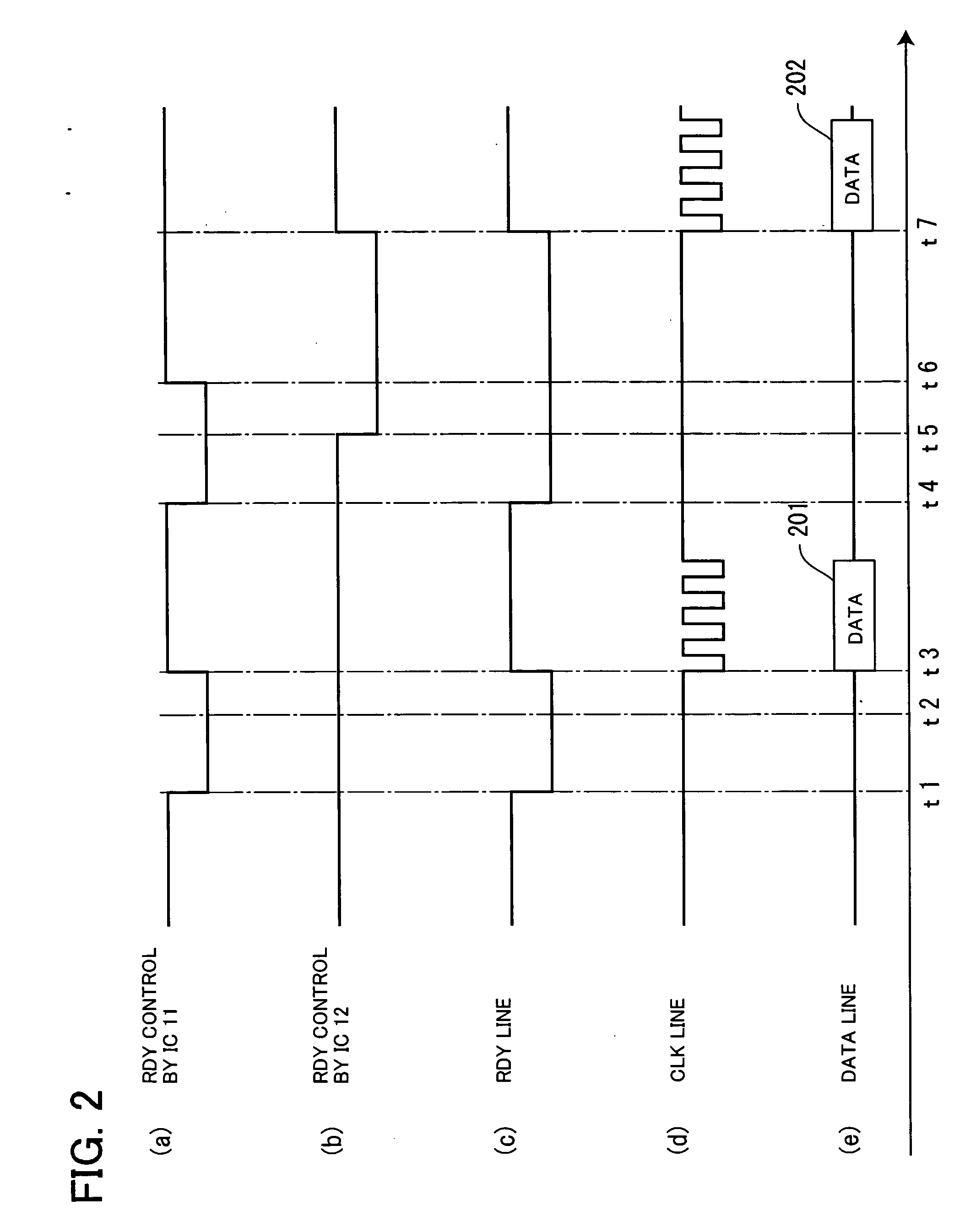
[0011] According to the above described construction, when the transmitting side device performs data transmission, the control signal transmission line which is kept to a high level (or low level) in a basic condition is driven low (or high) by the transmitting side device for a predetermined period (at least a period until the signal reaches the receiving side device), and therefore the receiving side device can recognize a communication period (time at which communication is started) and when the receiving side device is not ready for receiving data, the control signal transmission line is driven low (or high) until the receiving side device becomes ready for receiving data, and therefore the transmitting side device can judge whether the receiving side device cannot receive data (busy state or the like) (that is, perform a handshake).

Problems solved by technology

When these electronic devices are mounted on a printed circuit board, data transmission lines for mutual data transmission / reception are often constructed of a copper foil pattern formed on the printed circuit board and since the area of the substrate is limited due to requirements such as downsizing of the apparatus and cost reduction, a method of realizing data transmission / reception between electronic devices using a serial communication system is widely adopted (because adopting parallel communication requires many signal lines (which increases the area of the copper foil pattern) and leads to increases in the substrate area and cost)).
Moreover, since no handshake between the master (transmitting) side device 1301 and slave side device 1302 can be realized, if data is sent from the master side device 1301 during a (Busy) period during which the slave side device 1302 is not ready for receiving data, a receiving error may result.

Method used


Image

  • Electronic apparatus provided with electronic devices for serial communication and serial communication method
  • Electronic apparatus provided with electronic devices for serial communication and serial communication method
  • Electronic apparatus provided with electronic devices for serial communication and serial communication method

Examples


embodiment 1

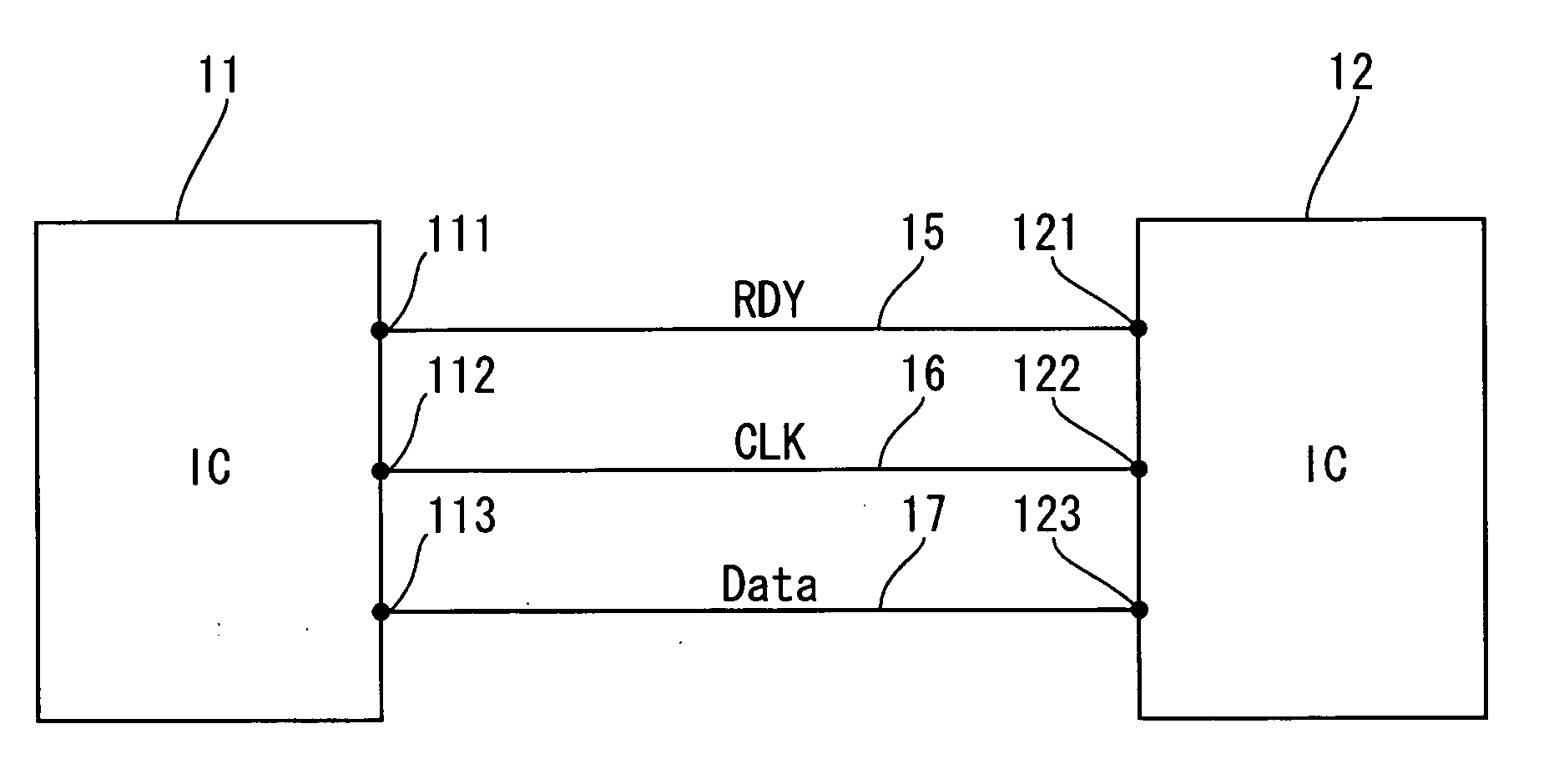
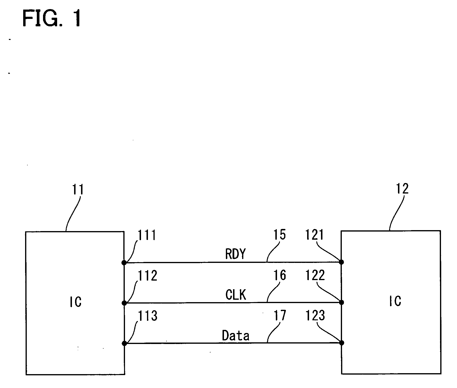
[0036]FIG. 1 is a block diagram showing an overview of parts (wiring for carrying out serial communication between ICs) of an electronic apparatus provided with a plurality of electronic devices (IC) of this embodiment related to the present invention. FIG. 2 is a timing chart illustrating the concept of serial communication related to the present invention.

[0037] As shown in FIG. 1, the electronic apparatus of this embodiment is provided with a plurality of electronic devices (IC 11, IC 12) and each IC is provided with CLK terminal 112 and CLK terminal 122 to which a clock signal line 16 for transmitting a clock signal to establish data synchronization is connected, Data terminal 113 and Data terminal 123 to which a data transmission line 17 for transmitting data to be transmitted / received is connected, and RDY terminal 111 and RDY terminal 121 to which a control signal transmission line 15 for transmitting a control signal for communication control is connected or the like.

[0038...

embodiment 2

[0048]FIG. 5 is a block diagram showing an overview of parts of an electronic apparatus provided with a plurality of electronic devices (ICs) of this embodiment related to the present invention (wiring for realizing serial communication between ICs). FIG. 6 is a timing chart illustrating the concept of serial communication related to the present invention. Components similar to those in Embodiment 1 are assigned the same reference numbers as those in Embodiment 1 and explanations thereof will be omitted here.

[0049] As shown in FIG. 5, this embodiment has basically the same configuration as that of Embodiment 1 (FIG. 1), but this embodiment provides two data transmission lines 17 (data transmission lines 17a and 17b) so as to realize full-duplex communication between an IC 11 and an IC 12.

[0050] Hereinafter, the concept of operation of data transmission / reception processing between the two ICs will be explained assuming that the IC 11 is a master (transmitting) side device and the ...

embodiment 3

[0058]FIG. 9 is a timing chart illustrating the concept of serial communication related to the present invention. An overview of the construction of an electronic apparatus provided with a plurality of electronic devices (ICs) of this embodiment is similar to that of Embodiment 2 (FIG. 5) and will be explained with reference to FIG. 5 as required.

[0059] Hereinafter, the concept of operation of data transmission / reception processing between two ICs will be explained assuming that the IC 11 (FIG. 5) is a master (transmitting) side device and IC 12 as a slave (receiving) side device. FIG. 10 and FIG. 11 are flow charts showing the concept of processing of parts of the IC 11 which is the master side device related to the present invention. FIG. 12 is a flow chart showing the concept of processing of parts of the IC 12 which is the slave side device related to the present invention. For the processing concept similar to that of Embodiment 1 (FIG. 3 or FIG. 4) or Embodiment 2 (FIG. 7 or ...


PUM


Abstract

The invention provides an electronic apparatus provided with electronic devices for carrying out data transmission / reception through serial communication, designed to maintain highly efficient data transmission and prevent communication errors. An RDY line 15 which is kept to a high level in a basic condition is provided and when this line is driven low by a transmitting side IC 11, a transmission request is transmitted to a receiving side IC 12 and upon receiving this request, the receiving side IC 12 drives the RDY line 15 to a low level until the own preparations for receiving data are completed, while the transmitting side IC 11 performs no data transmission until the RDY line 15 is driven high after the transmission of the transmission request, and in this way the transmitting side IC 11 and receiving side IC 12 perform a handshake.

Description

[0001] The present application is based on and claims priority of Japanese patent application No. 2005-213860 filed on Jul. 25, 2005, the entire contents of which are hereby incorporated by reference. BACKGROUND OF THE INVENTION [0002] 1. Field of the Invention [0003] The present invention relates to an electronic apparatus provided with electronic devices which performs data transmission / reception through serial communication, and more particularly, to an electronic apparatus with improved efficiency of serial communication. [0004] 2. Description of the Related Art [0005] There are many types of electronic apparatuses provided with a plurality of electronic devices (IC or the like) and data needs to be transmitted / received between these electronic devices for the apparatus to operate. When these electronic devices are mounted on a printed circuit board, data transmission lines for mutual data transmission / reception are often constructed of a copper foil pattern formed on the printe...

Claims


Application Information

Patent Timeline
IPC IPC(8): G06F13/00
CPCG06F13/4282
Inventor NISHINO, TOSHIO
Owner ORION ELECTRIC CO LTD
Learn More