Vehicular hydraulic system with dual relief valve

a hydraulic system and relief valve technology, applied in the direction of fluid couplings, servomotors, instruments, etc., can solve the problems of difficulty in using vacuum assist braking systems, aftermarket demand for hydraulic braking assist systems, and inconvenient use of vacuum assist systems, so as to achieve compact and space efficient, cost-saving

Inactive Publication Date: 2008-03-20
STEERING SOLUTIONS IP HLDG +1
View PDF1 Cites 11 Cited by
  • Summary
  • Abstract
  • Description
  • Claims
  • Application Information

AI Technical Summary

Benefits of technology

[0012]An advantage of the present invention is that it provides a compact and space efficient valve structure for providing pressure relief for two separate hydraulic applications that are arranged in series.
[0013]Another advantage of the invention is that, in some embodiments of the invention, the relief pressure for the two separate hydraulic applications may be at differing pressure values.
[0014]For example, such a dual relief valve may be used in a vehicular hydraulic system to provide an integrated hydraulic brake and steering gear assist system that includes a steering gear assist device having a lower pressure limit value than the brake assist device to thereby provide cost savings in comparison to the use of a steering gear assist device having a hydraulic pressure relief value at least as large as the brake assist device.

Problems solved by technology

The use of vacuum assist braking systems can be problematic in vehicles having a turbo-charged engine and such vehicles will also often employ hydraulic braking assist systems.
Furthermore, there is an aftermarket demand for hydraulic braking assist systems for vehicles, such as hotrods, that may not otherwise have a brake assist device or for which the use of a vacuum assist system presents difficulties.
Because of the series arrangement, the application of the brakes and engagement of the hydraulic braking assist system can affect the flow of hydraulic fluid to the steering gear, thereby affecting the amount of assist available to the steering gear.
Specifically, when a heavy braking load is applied, it causes an increase in backpressure to the pump which can exceed a threshold relief pressure (e.g., 1,500 psi) of the pump.
During this relief condition, a diminished flow of fluid is sent to the steering gear which may result in a detectable increase in steering effort by the operator of the vehicle to turn the steering wheel under extreme relief conditions.
Thus, the requirement that the steering gear assist device have a pressure relief value that is at least as large as the pressure relief value of the brake assist device often has a direct impact on the selection of a steering gear assist device and results in the selection of a more expensive steering gear assist device.

Method used


Image

  • Vehicular hydraulic system with dual relief valve
  • Vehicular hydraulic system with dual relief valve
  • Vehicular hydraulic system with dual relief valve

Examples


Embodiment Construction

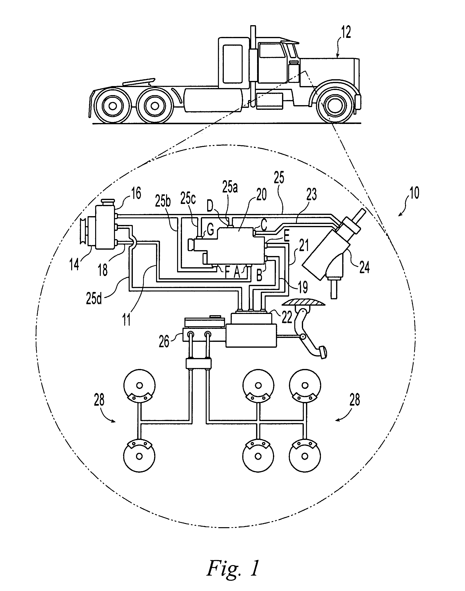
[0022]FIG. 1 shows a hydraulic system 10 for a vehicle 12 for assisting in the steering and braking of the vehicle. The hydraulic system includes a hydraulic pump 14 and reservoir 16. The reservoir may be incorporated into the pump 14, as illustrated, or may be located remote from the pump 14.

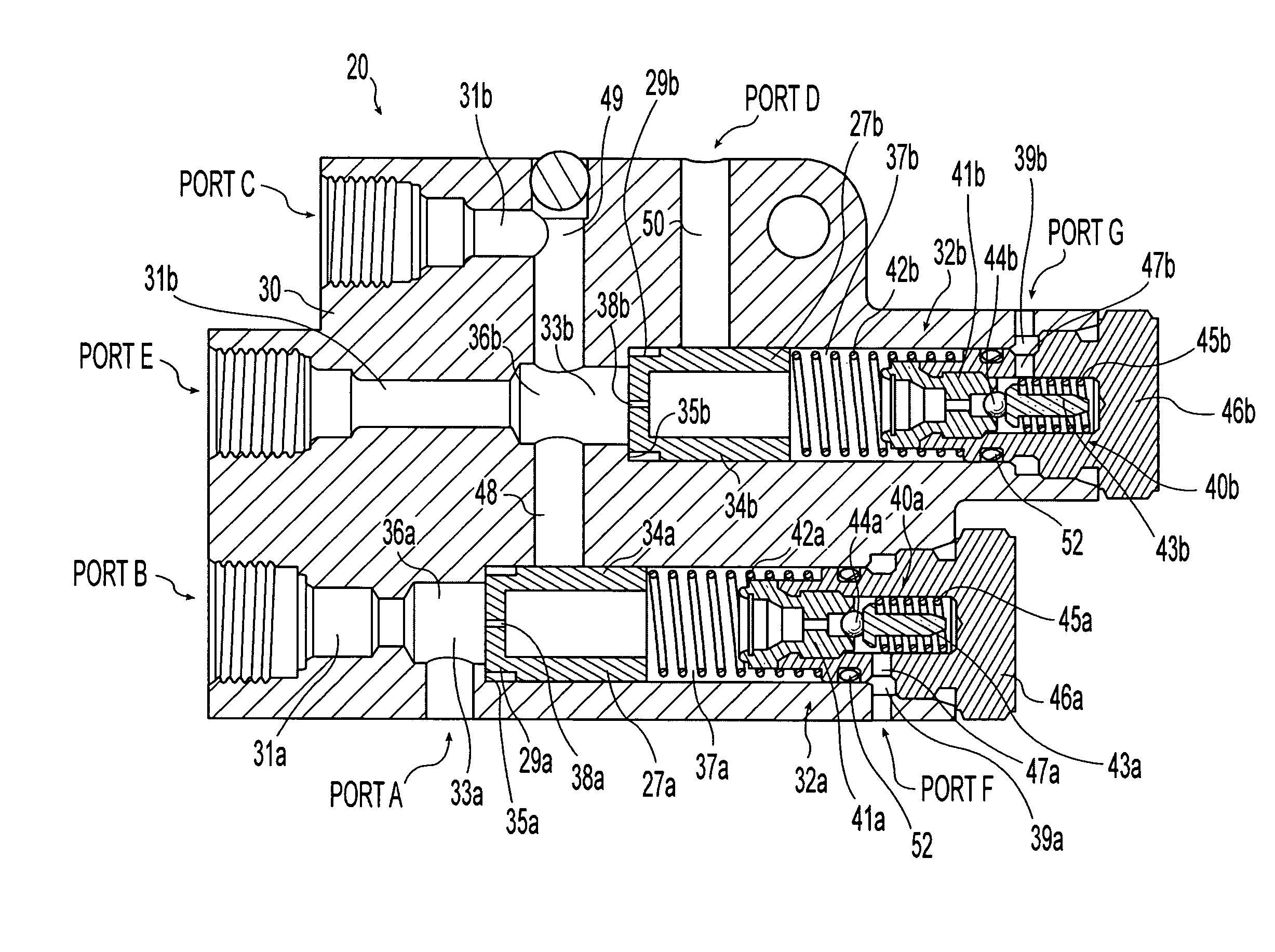
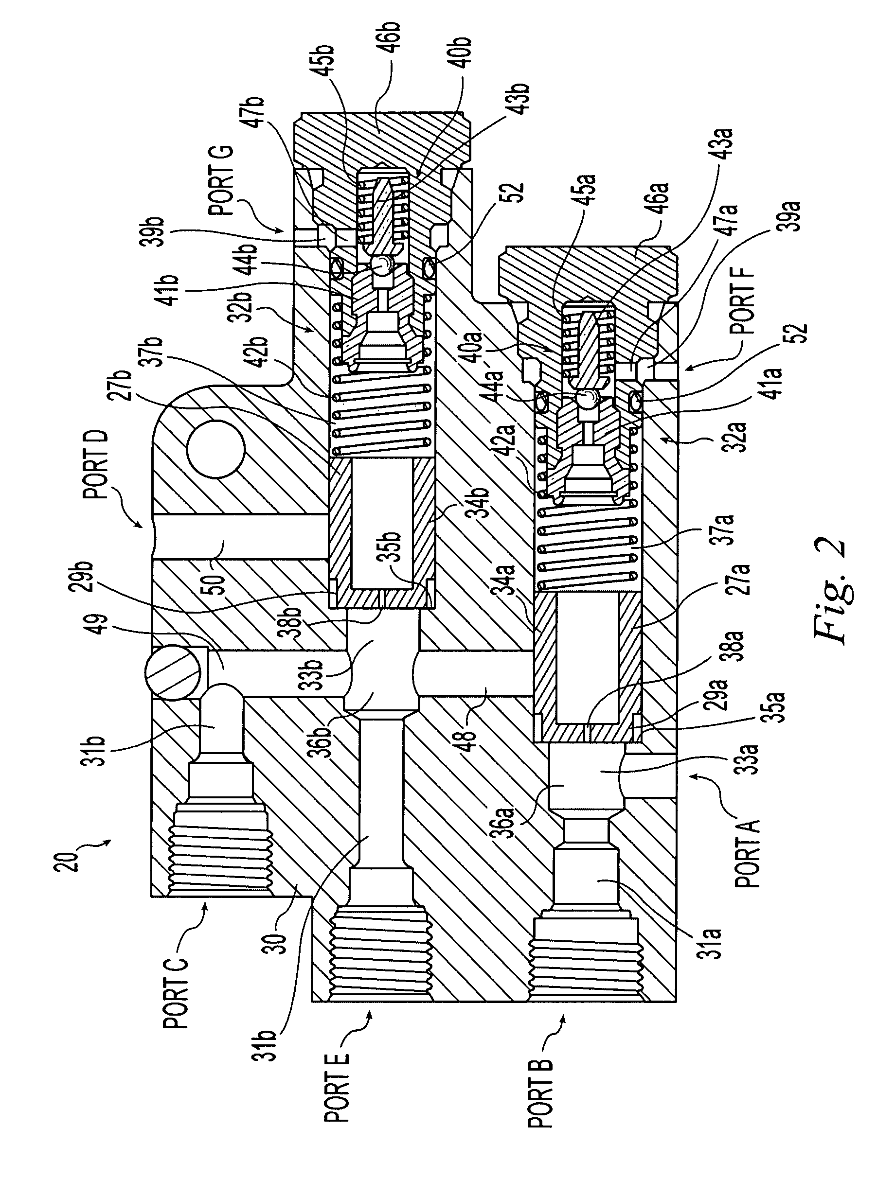
[0023]The pump 14 delivers high pressure hydraulic fluid through discharge line 18 to a dual relief valve 20. The dual relief valve 20, in turn, communicates with a first hydraulic application 22, a second hydraulic application 24, and the reservoir 16, in a manner that depends on the operating conditions of the system 10, as will be explained below.

[0024]The first and second hydraulic applications 22, 24 take the form of a hydraulic device or a hydraulic sub-circuit. In the illustrated embodiment, first application 22 is a hydraulic braking assist system or booster device, and the second application 24 is a hydraulic steering gear assist system or device.

[0025]The hydraulic brake booster devic...


PUM


Abstract

A vehicular hydraulic system having a hydraulic pump and first and second hydraulic applications arranged in series. A dual relief valve defines first and second flow channels, a passageway and a bypass port. The first flow channel is disposed between the hydraulic pump and the first hydraulic application and the second flow channel is disposed between the first hydraulic application and the second hydraulic application. A first valve member controls fluid flow through the passageway and allows fluid flow from the first to the second flow channel through the passageway when fluid pressure within the first flow channel exceeds a first threshold pressure. A second valve member controls fluid flow through the bypass port and allows fluid flow from the second flow channel to a return line through the bypass port when fluid pressure within the second flow channel exceeds a second threshold pressure.

Description

CROSS REFERENCE TO RELATED APPLICATIONS[0001]This application claims priority under 35 U.S.C. 119(e) of U.S. provisional patent application Ser. No. 60 / 846,035 filed on Sep. 20, 2006 entitled DUAL RELIEF VALVE FOR VEHICULAR HYDRAULIC SYSTEM the disclosure of which is hereby incorporated herein by reference.BACKGROUND OF THE INVENTION[0002]1. Field of the Invention[0003]The present invention relates to hydraulic systems for vehicles and, more particularly, to a hydraulic system having a hydraulic fluid pump and at least two hydraulic applications.[0004]2. Description of the Related Art[0005]Many trucks with hydraulic braking systems, particularly larger gasoline powered and diesel powered trucks, incorporate hydraulic braking assist systems, rather than vacuum assist systems commonly found in passenger automobiles. The use of vacuum assist braking systems can be problematic in vehicles having a turbo-charged engine and such vehicles will also often employ hydraulic braking assist sys...

Claims


Application Information

Patent Timeline
Patent Type & Authority Applications(United States)
IPC IPC(8): F15B15/00F16K17/00G05D11/02
CPCB60T13/162Y10T137/2605
Inventor DAVISON, JAMES L.WEBBER, KENNETH P.LINCOLN, RICK L.WONG, ALBERT C.
Owner STEERING SOLUTIONS IP HLDG
Why Eureka
Try Eureka