System and method for implementing balanced RF fields in an ion trap device

a technology of balanced radiofrequency and ion trap, which is applied in the direction of mass spectrometer, stability-of-path spectrometer, separation process, etc., can solve the problems of increasing the requirements for enhanced device functionality and performance, increasing the requirements for system functionality, and requiring additional resources. to achieve the effect of effective implementation of balanced rf fields

Active Publication Date: 2008-03-20
THERMO FINNIGAN
View PDF6 Cites 9 Cited by
  • Summary
  • Abstract
  • Description
  • Claims
  • Application Information

AI Technical Summary

Benefits of technology

[0008]In certain embodiments, a Y electrode separation distance may be defined along a Y axis that runs between the Y electrodes through the centerline. Similarly, an X electrode separation distance may be defined along an X axis that runs between the X electrodes through the centerline. In certain embodiments, the compensation feature is provided by the ion trap being “stretched” in the X axis direction by causing the X separation distance to be greater than the Y separation distance. This stretching procedure in the X axis direction has the beneficial effect of compensating for the ejection slots to provide more linear field characteristics or to minimize the non-linear field components within the ion trap device.
[0011]In accordance with the present embodiment, utilizing the foregoing non-matching RF signals in the X axis direction and the Y axis direction advantageously results in a balanced potential of approximately zero Volts at the centerline of the ion trap device. For at least the foregoing reasons, the present invention provides an improved system and method for effectively implementing balanced RF fields in an ion trap.

Problems solved by technology

However, effectively performing analysis procedures with electronic devices may create substantial challenges for system designers.
For example, increased demands for enhanced device functionality and performance may require more system functionality and require additional resources.
An increase in functionality or other requirements may also result in a corresponding detrimental economic impact due to increased production costs and operational inefficiencies.
The utilization of such ejection slots may cause the electromagnetic field characteristics of the ion trap to exhibit certain undesired non-linear properties.
Altering physical dimensions of an ion trap may improve non-linear field characteristics, but may also result in an unbalanced centerline potential in the ion trap.
Such an unbalanced centerline potential may cause various performance problems during operation of the ion trap.
For example, ion injection procedures for inserting an ionized test sample into the ion trap may be negatively affected when incoming ions are subject to an unbalanced centerline potential.
This unbalanced centerline potential may result in poor injection efficiency or significant mass bias in the trapping efficiency of ion trap devices.
However, these voltages and their effects are not necessarily exclusive.

Method used


Image

  • System and method for implementing balanced RF fields in an ion trap device
  • System and method for implementing balanced RF fields in an ion trap device
  • System and method for implementing balanced RF fields in an ion trap device

Examples


Embodiment Construction

[0025]The present invention relates to an improvement in analytical instrumentation techniques. The following descriptions and illustrations are presented to enable one of ordinary skill in the art to make and use the invention and is provided in the context of a patent application and its requirements. Various modifications to the disclosed embodiments will be apparent to those skilled in the art, and the generic principles herein may be applied to other embodiments. Thus, the present invention is not intended to be limited to the embodiments shown, but is to be accorded the widest scope consistent with the principles and features described herein.

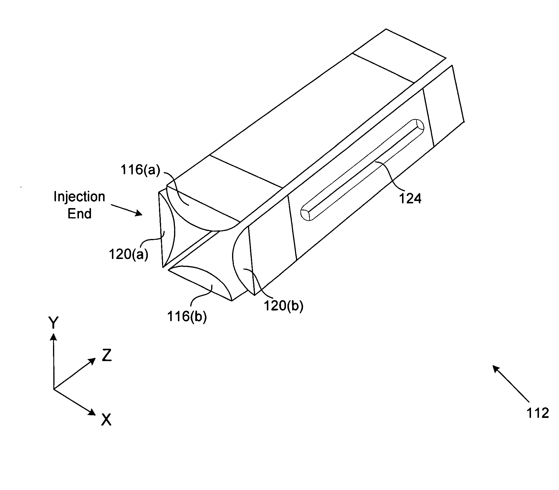
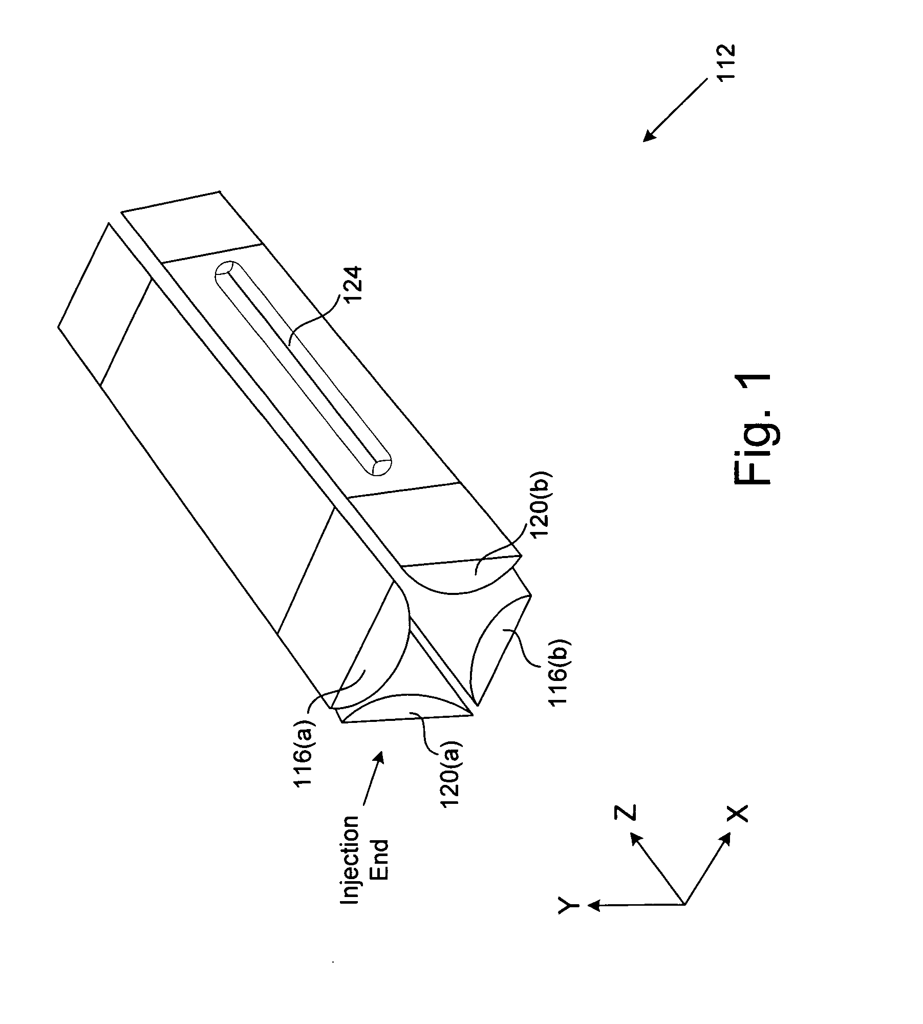
[0026]Referring now to FIG. 1, an elevation view of an ion trap 112 is shown, in accordance with one embodiment of the present invention. In alternate embodiments, the embodiments of FIGS. 1-12 may be implemented using components and configurations in addition to, or instead of, certain of those components and configurations discussed in ...


PUM


Abstract

A system and method are disclosed for effectively compensating for an unbalanced or non-zero centerline radio-frequency potential in a quadrupolar ion trap, the unbalanced centerline potential created by a compensation feature that minimizes non-linear field components created by one or more ejection slots in the ion trap. The ion trap includes a centerline that passes longitudinally through a trapping volume inside of the ion trap, a pair of Y electrodes with inner Y electrode surfaces that are approximately parallel to the centerline, and a pair of X electrodes with inner X electrode surfaces that are approximately parallel to the centerline. The X electrodes have ejection slots through which trapped ions are ejected from the ion trap. A Y signal with a Y signal amplitude is coupled to both of the Y electrodes. An X signal with an X signal amplitude is coupled to both of the X electrodes. The X signal amplitude is selected to be greater than the Y signal amplitude to thereby create a balanced centerline potential at the centerline of the ion trap device.

Description

FIELD OF THE INVENTION[0001]The disclosed embodiments of the present invention relate generally to techniques for implementing an ion trap device, and relate more particularly to a system and method for implementing balanced radio-frequency (RF) fields in an ion trap device.BACKGROUND OF THE INVENTION[0002]Developing effective methods for implementing analytical instrumentation is a significant consideration for designers and manufacturers of contemporary electronic analytical devices. However, effectively performing analysis procedures with electronic devices may create substantial challenges for system designers. For example, increased demands for enhanced device functionality and performance may require more system functionality and require additional resources. An increase in functionality or other requirements may also result in a corresponding detrimental economic impact due to increased production costs and operational inefficiencies.[0003]Furthermore, system capability to pe...

Claims


Application Information

Patent Timeline
Patent Type & Authority Applications(United States)
IPC IPC(8): H01J49/42
CPCH01J49/423
Inventor SCHWARTZ, JAE C.
Owner THERMO FINNIGAN
Why Eureka
Try Eureka