
Charged particle beam irradiation system and charged particle beam extraction method

a charge beam and beam irradiation technology, applied in the field of charge beam irradiation system and charged particle beam extraction method, can solve the problems of difficulty in smoothly carrying out treatment for a larger number of patients, and achieve the effect of reducing the probability of erroneous irradiation, and easy adjustmen

Inactive Publication Date: 2008-03-20
HITACHI LTD
View PDF18 Cites 111 Cited by
  • Summary
  • Abstract
  • Description
  • Claims
  • Application Information

AI Technical Summary

Benefits of technology

[0010]An object of the present invention is to provide a charged particle beam irradiation system and a charged particle beam extraction method which can reduce the probability of erroneous irradiation of a charged particle beam in the direction of advance of the charged particle beam.
[0013]With the feature of the present invention of stopping the supply of the charged particle beam to one or more of the plurality of zones divided in the rotating direction in each of which the target dose is attained, and of allowing the supply of the charged particle beam to one or more other zones in each of which the target dose is not yet attained, beam doses can be easily adjusted at various positions within an irradiation target in the direction of advance of the charged particle beam. It is therefore possible to greatly reduce the probability of erroneous irradiation that the beam dose becomes excessive or deficient at various positions within the irradiation target in the direction of advance of the charged particle beam. Thus, a dose distribution within the irradiation target in the direction of advance of the charged particle beam can be easily adjusted to the desired one. Preferably, that probability can be reduced to zero.
[0014]According to the present invention, it is possible to greatly reduce the probability of erroneous irradiation that the beam dose becomes excessive or deficient at various positions within the irradiation target in the direction of advance of charged particles. As a result, a dose distribution within the irradiation target in the direction of advance of the charged particle beam can be easily adjusted to the desired one.

Problems solved by technology

Hence a difficulty has been experienced in smoothly carrying out treatments for a larger number of patients.

Method used


Image

  • Charged particle beam irradiation system and charged particle beam extraction method
  • Charged particle beam irradiation system and charged particle beam extraction method
  • Charged particle beam irradiation system and charged particle beam extraction method

Examples


Embodiment Construction

[0027]One preferred embodiment of the present invention will be described in detail below with reference to the drawings.

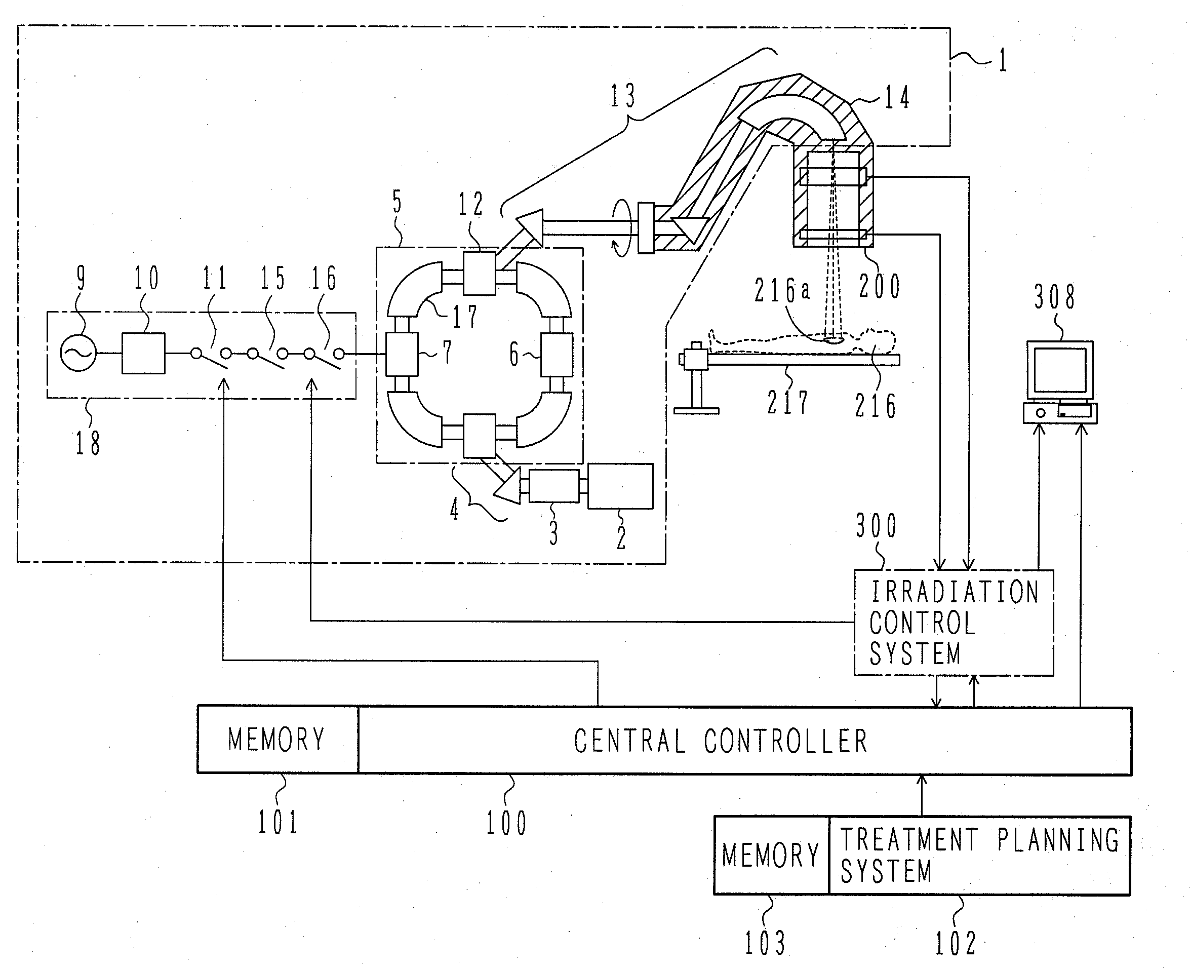
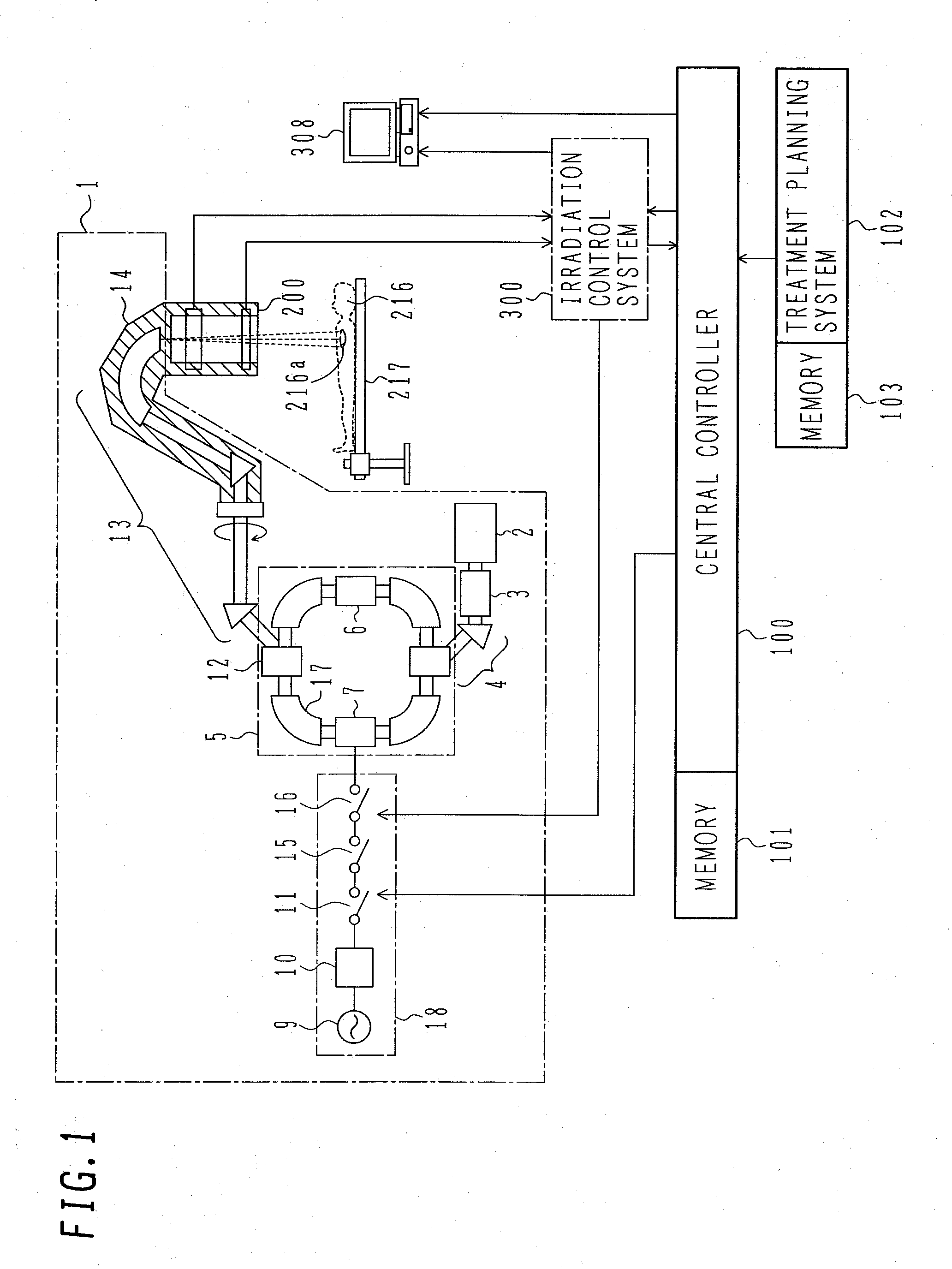
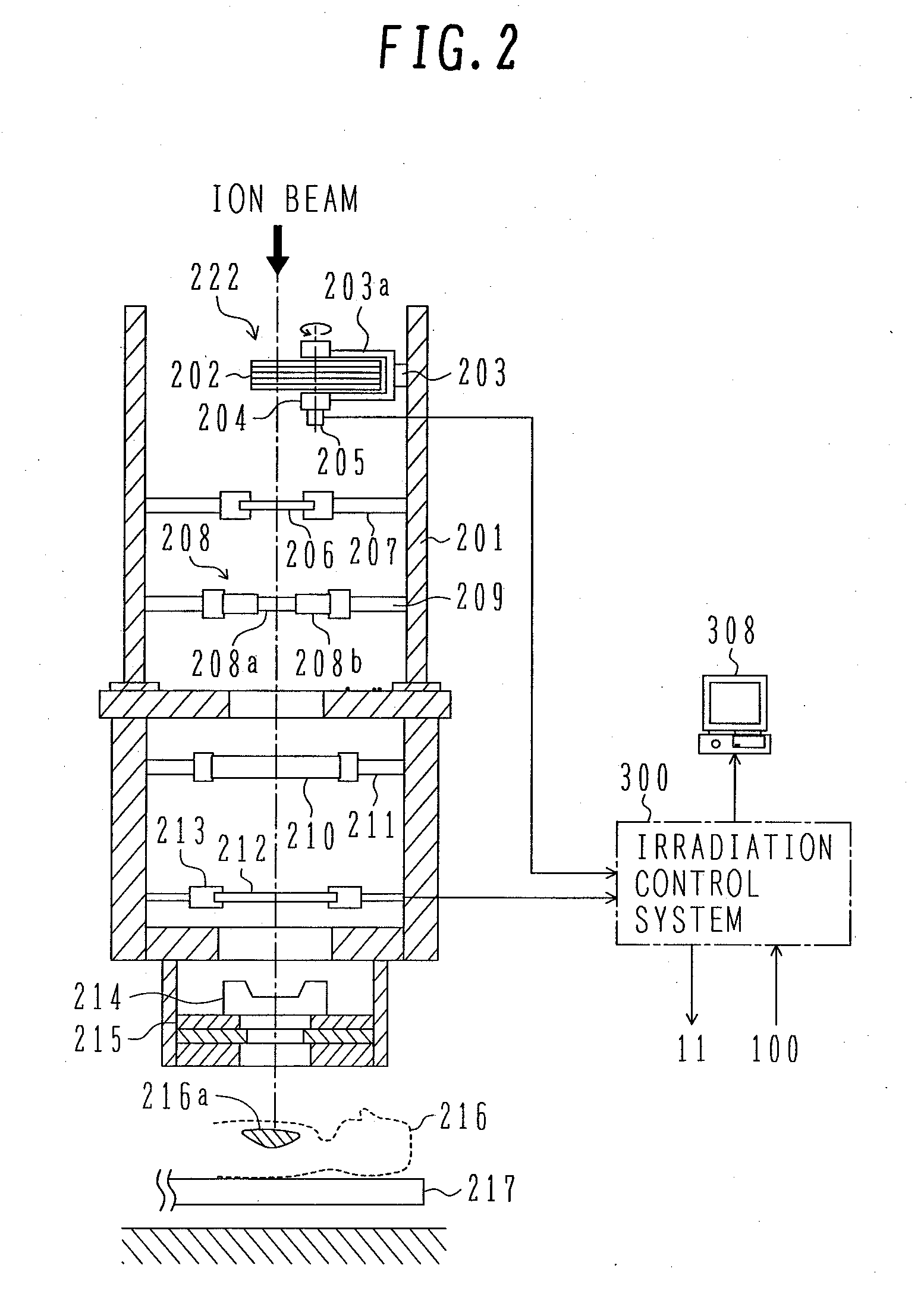
[0028]As shown in FIG. 1, in a particle beam therapy system (ion beam irradiation system) according to this embodiment, an ion beam (e.g., a proton beam) is irradiated to an affected part 216a in the body of a patient 216 who is kept fixed on a treatment bed 217. The ion beam irradiation system comprises an ion beam generator (e.g., a proton beam generator or a particle beam generator) 1, a central controller 100, an irradiation apparatus 200, and an irradiation control system 300.

[0029]The central controller 100 reads irradiation conditions (such as the direction of beam irradiation, the SOBP width, the dose, the maximum irradiation depth, and the irradiation field size) which are decided in a treatment planning system 102 to form an irradiation field optimum for the affected part 216a in the body of the patient 216. Then, the central controller 100 selects opera...


PUM


Abstract

A charged particle beam irradiation system and a charged particle beam extraction method which can prevent erroneous irradiation of a charged particle beam in the direction of advance of the charged particle beam. The system and method are featured in stopping supply of an ion beam to one or more of a plurality of angle zones in each of which a target dose is attained, the angle zones being formed by dividing an RMW in a rotating direction thereof, and in allowing the supply of the ion beam to one or more other angle zones in each of which a target dose is not yet attained. The invention can easily adjust beam doses at various positions in an affected part of the patient body in the direction of advance of the ion beam, and can greatly reduce the probability of erroneous irradiation that the beam dose becomes excessive or deficient at the various positions within the affected part of the patient body in the direction of advance of the ion beam.

Description

BACKGROUND OF THE INVENTION[0001]1. Field of the Invention[0002]The present invention relates to a charged particle beam irradiation system and a charged particle beam extraction method. More particularly, the present invention relates to a charged particle beam irradiation system and a charged particle beam extraction method suitable for use as a particle beam therapy system in which an ion beam of, e.g., protons and carbon ions, is irradiated to an affected part in the body of a patient for treatment.[0003]2. Description of the Related Art[0004]There is known a therapy method for irradiating an ion beam (charged particle beam) of, e.g., protons or carbon ions, to an affected part of in the body of a patient, such as a cancer. An ion beam irradiation system for use in such therapy comprises a circular accelerator, a beam transport, and rotating irradiation equipment which includes an irradiation apparatus. The circular accelerator accelerates an ion beam circulating along an orbit ...

Claims


Application Information

Patent Timeline
IPC IPC(8): G01K1/08
CPCA61N5/1048A61N5/1065A61N2005/1087H05H7/10A61N2005/1096G21K1/10A61N2005/1095
Inventor NIHONGI, HIDEAKIMATSUDA, KOJIHIRAMOTO, KAZUOAKIYAMA, HIROSHI
Owner HITACHI LTD
Learn More