Arrangement for generating extreme ultraviolet radiation from a plasma generated by an energy beam with high conversion efficiency and minimum contamination

a technology of energy beam and plasma, which is applied in the direction of optical radiation measurement, instruments, therapy, etc., can solve the problems of undesirable out-of-band radiation components, insufficient efficiency of clean fuels (target materials such as xenon), and all carrier liquids or solvents known for this purpose contain component parts, and achieve the effect of long life of the injection devi

Inactive Publication Date: 2008-03-20
USHIO DENKI KK
View PDF16 Cites 44 Cited by
  • Summary
  • Abstract
  • Description
  • Claims
  • Application Information

AI Technical Summary

Benefits of technology

[0012]It is the primary object of the invention to find a novel possibility for generating EUV radiation by means of a plasma induced by an energy beam that pen-nits a more efficient conversion of the energy radiation into EUV radiation in the wavelength region of 13.5 nm by using metallic target material without

Problems solved by technology

Known “clean fuels” (target materials such as xenon) are not sufficiently efficient for the generation of EUV radiation based on a plasma which is excited by a pulsed energy beam for emitting in the EUV spectral band around 13.5 nm because their conversion efficiency (ratio of the emitted energy in the desired EUV spectral band to the (laser) excitation energy) is only about 1%.
These out-of-band radiation components are undesirable because they contribute to unnecessary heating of the optics and other source components.
However, it is d

Method used


Image

  • Arrangement for generating extreme ultraviolet radiation from a plasma generated by an energy beam with high conversion efficiency and minimum contamination
  • Arrangement for generating extreme ultraviolet radiation from a plasma generated by an energy beam with high conversion efficiency and minimum contamination
  • Arrangement for generating extreme ultraviolet radiation from a plasma generated by an energy beam with high conversion efficiency and minimum contamination

Examples


Embodiment Construction

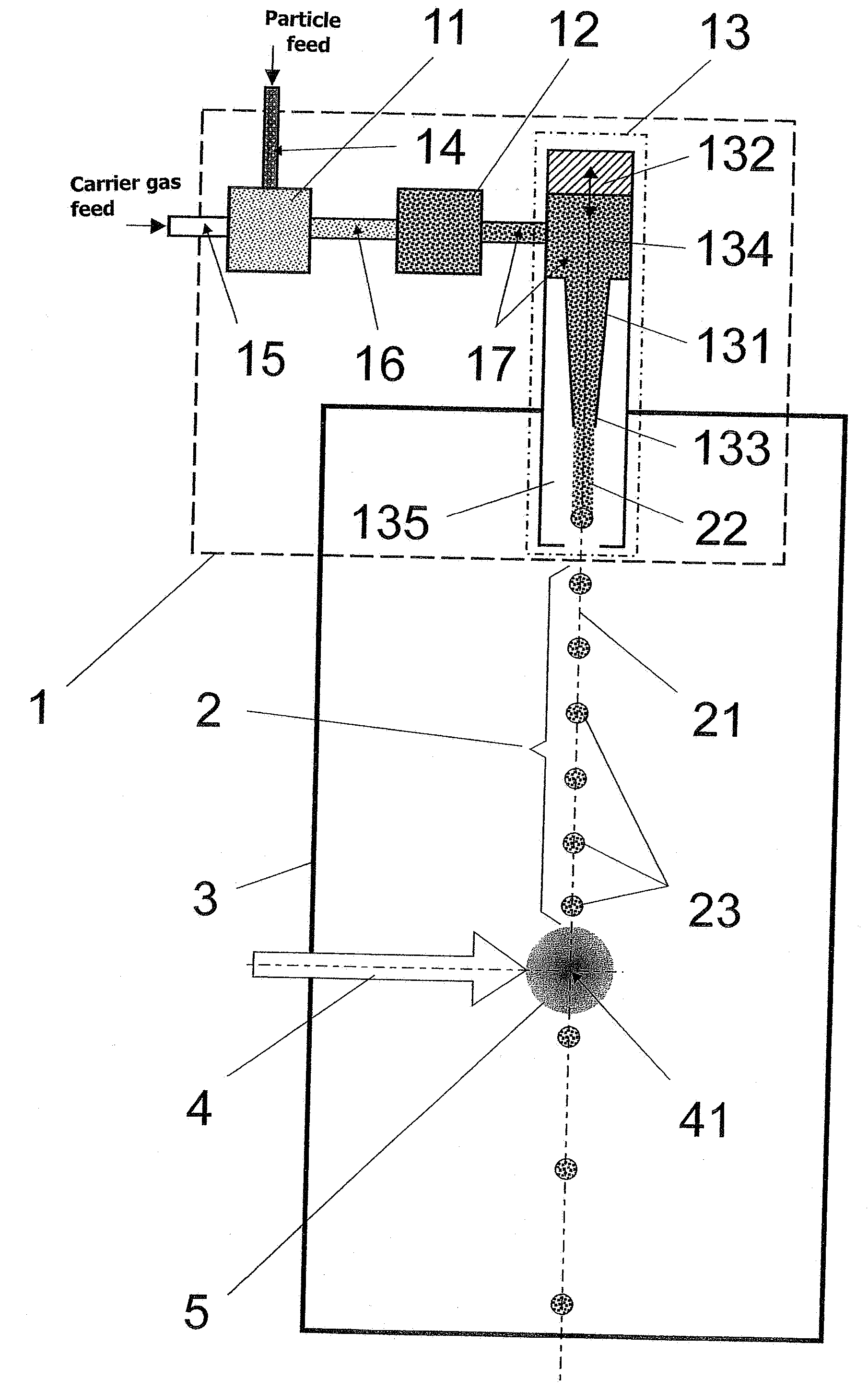
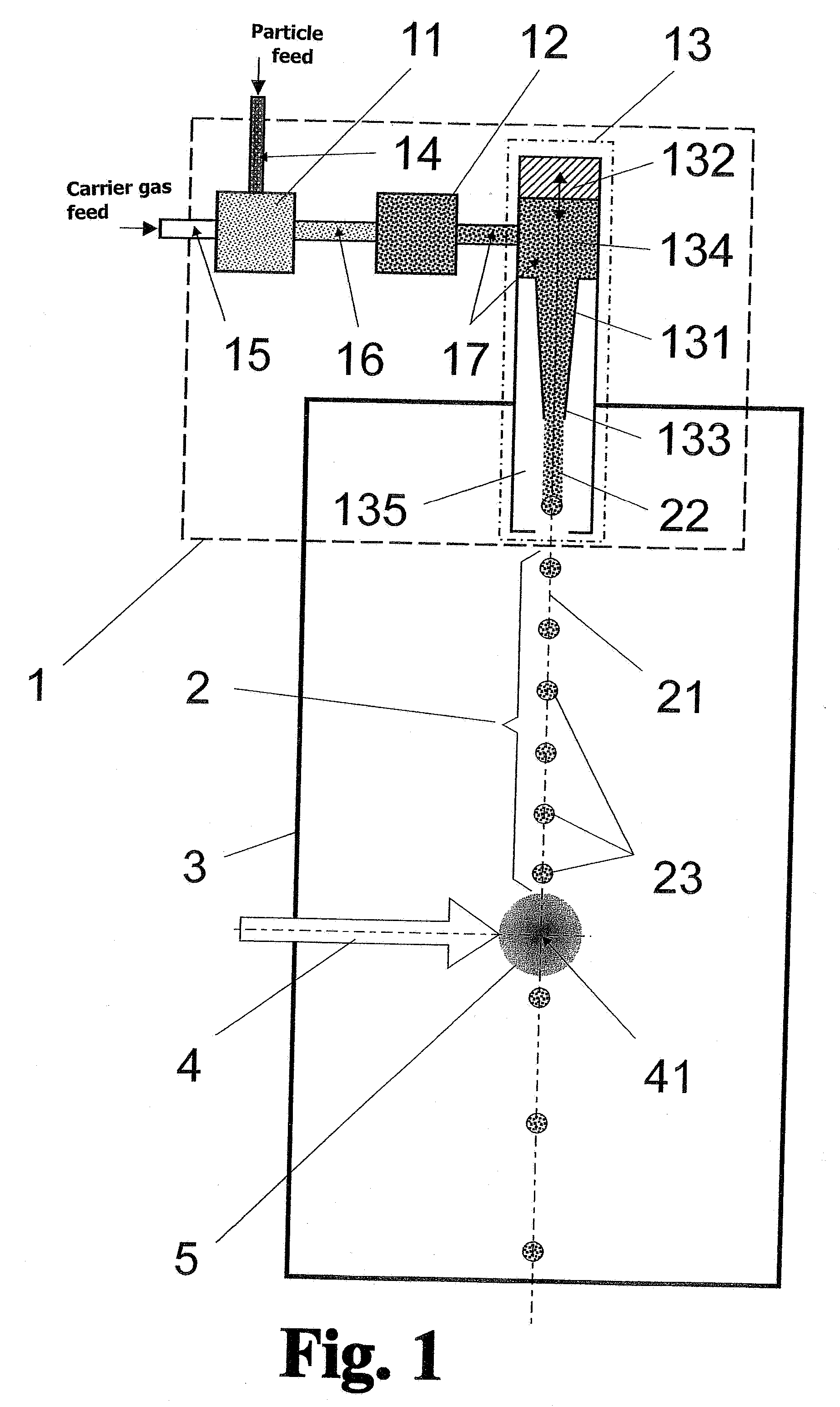
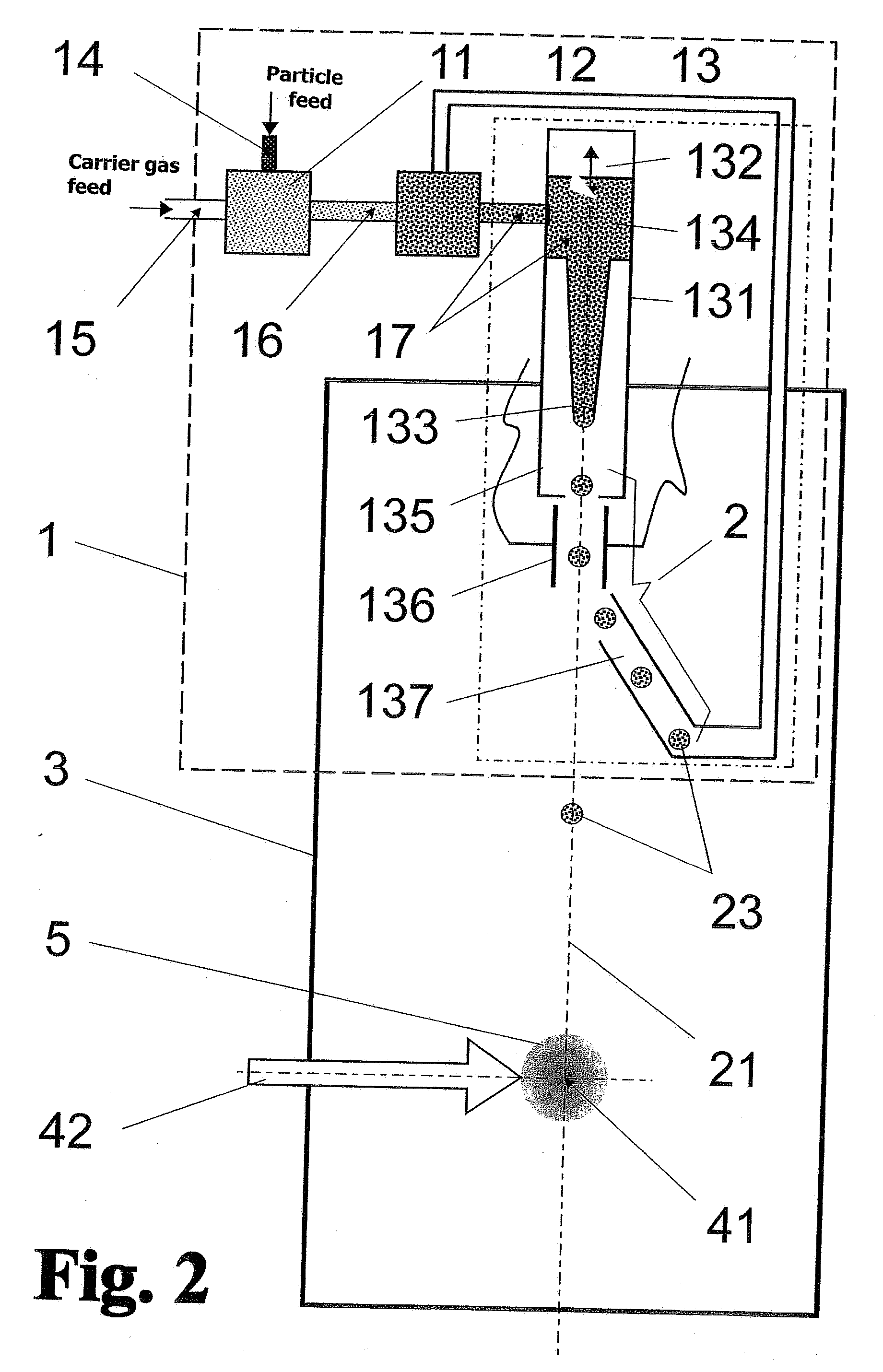
[0044]The EUV radiation source has a target feed device 1 which, as is shown schematically in FIG. 1, basically contains a mixing chamber 11, a liquefaction chamber 12 and an injection unit 13. The injection unit 13 has a droplet generator 131, a pressure modulator 132, a target nozzle 133, and a nozzle chamber 134.

[0045]Solid particles 14 comprising metals or metal compounds, e.g., tin or lithium (or preferably also their oxides, SnO, SnO2, LiO, LiO2) which emit efficiently in the EUV spectral region (around 13.5 nm) and a clean (i.e., free from emitting particles) carrier gas 15, e.g., noble gases or nitrogen, are combined and mixed in the mixing chamber 11. The resulting particle-containing mixture 16 is fed to the liquefaction chamber 12, wherein liquefaction is carried out at low temperatures (T 1 bar. Sn particles (individual particles of at most 10 μm in size) are preferably mixed in to achieve a high efficiency of EUV generation (≈3%). However, mixtures of other elements (e....


PUM


Abstract

The invention is directed to an arrangement for generating extreme ultraviolet radiation from a plasma generated by an energy beam with high conversion efficiency, particularly for application in radiation sources for EUV lithography. It is the object of the invention to find a novel possibility for generating EUV radiation by means of a plasma induced by an energy beam that permits a more efficient conversion of the energy radiation into EUV radiation in the wavelength region of 13.5 nm and ensures a long lifetime of the optical components and the injection device. According to the invention, this object is met by using a mixture of particles with a carrier gas and the target feed device has a gas liquefaction chamber, wherein the target material is supplied to the injection unit as a mixture of solid particles in liquefied carrier gas, and a droplet generator is provided for generating a defined droplet size and series of droplets, wherein means which are controllable in a frequency-dependent manner and which are triggered by the pulse frequency of the energy beam are connected to the injection unit for the series of droplets.

Description

CROSS-REFERENCE TO RELATED APPLICATION[0001]This application claims priority of German Application No. 10 2006 017 904.8, filed Apr. 13, 2006, the complete disclosure of which is hereby incorporated by reference.BACKGROUND OF THE INVENTION[0002]a) Field of the Invention[0003]The invention is directed to an arrangement for generating extreme ultraviolet radiation from a plasma generated by an energy beam with high conversion efficiency in which a pulsed energy beam is directed in a plasma generation chamber to a location where it interacts with a target, a target feed device contains a mixing chamber for generating a mixture of particles of an emission-efficient target material with at least one carrier gas and an injection unit for dispensing individually defined target volumes into the plasma generation chamber in a metered manner in order to supply only as much emission-efficient target material to the interaction location as can be converted into radiation by an energy pulse. The...

Claims


Application Information

Patent Timeline
IPC IPC(8): G01J3/10
CPCH05G2/003H05G2/005H05G2/008
Inventor KLOEPFEL, DIETHARDGAEBEL, KAI
Owner USHIO DENKI KK
Why Eureka
Try Eureka