Coupled Ring Oscillator and Method for Laying Out the Same

a ring oscillator and ring oscillator technology, applied in the direction of oscillator generators, pulse generation by logic circuits, pulse techniques, etc., can solve the problems of difficult to generate highly accurate phase information, inverter circuits are thus under heavy load, and the wire length of some signal wires is extremely increased, so as to achieve high accuracy and fine phase information, easy to form

Active Publication Date: 2008-03-20
SOCIONEXT INC
View PDF9 Cites 7 Cited by
  • Summary
  • Abstract
  • Description
  • Claims
  • Application Information

AI Technical Summary

Benefits of technology

[0020] As described above, the inventive coupled ring oscillator generates highly accurate and fine phase infor

Problems solved by technology

However, in the conventional layout in which the respective inverter circuits in the ring oscillators are connected by the phase-coupling circuits, the wire length of some of the signal wires is extremely increased

Method used


Image

  • Coupled Ring Oscillator and Method for Laying Out the Same
  • Coupled Ring Oscillator and Method for Laying Out the Same
  • Coupled Ring Oscillator and Method for Laying Out the Same

Examples


first embodiment

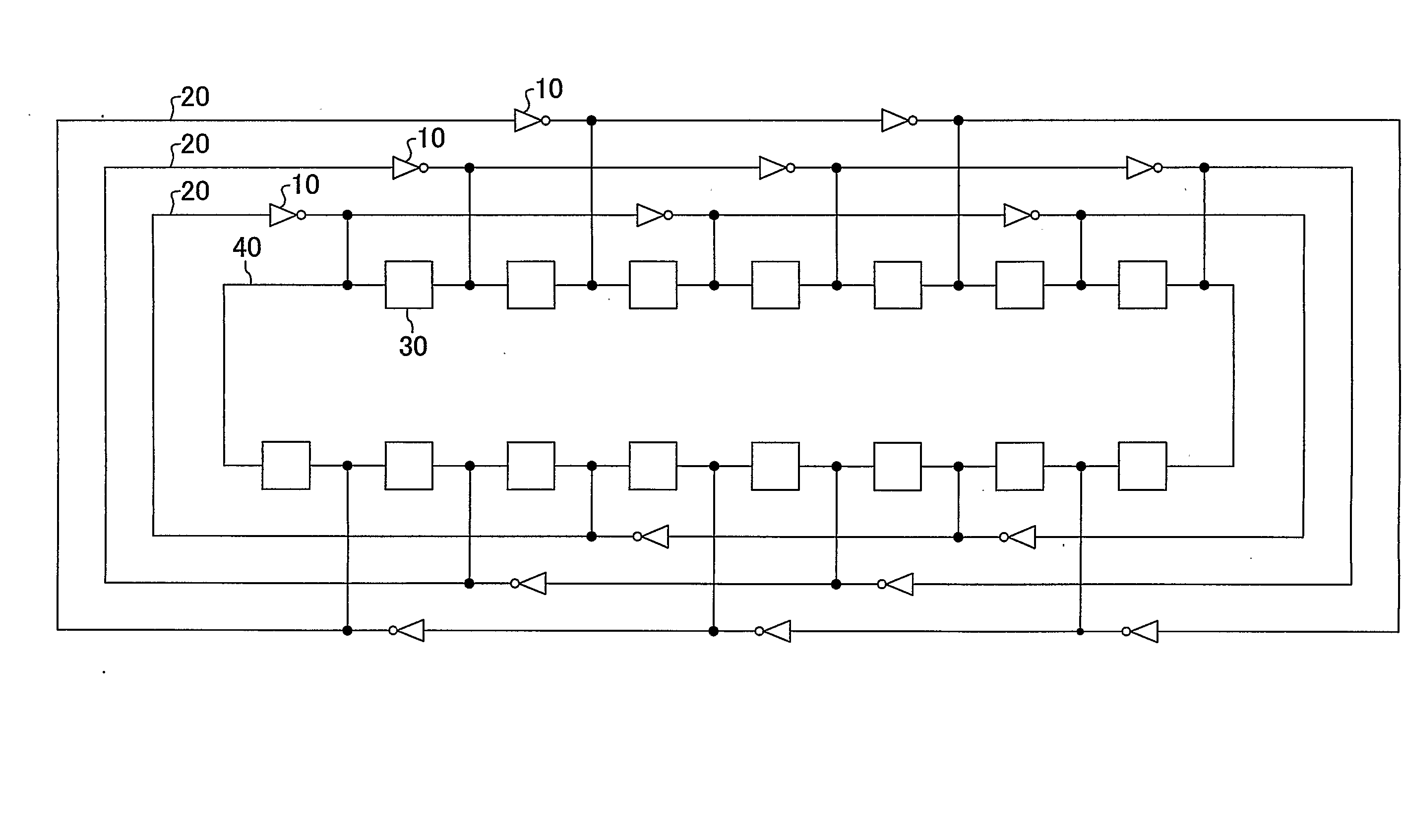
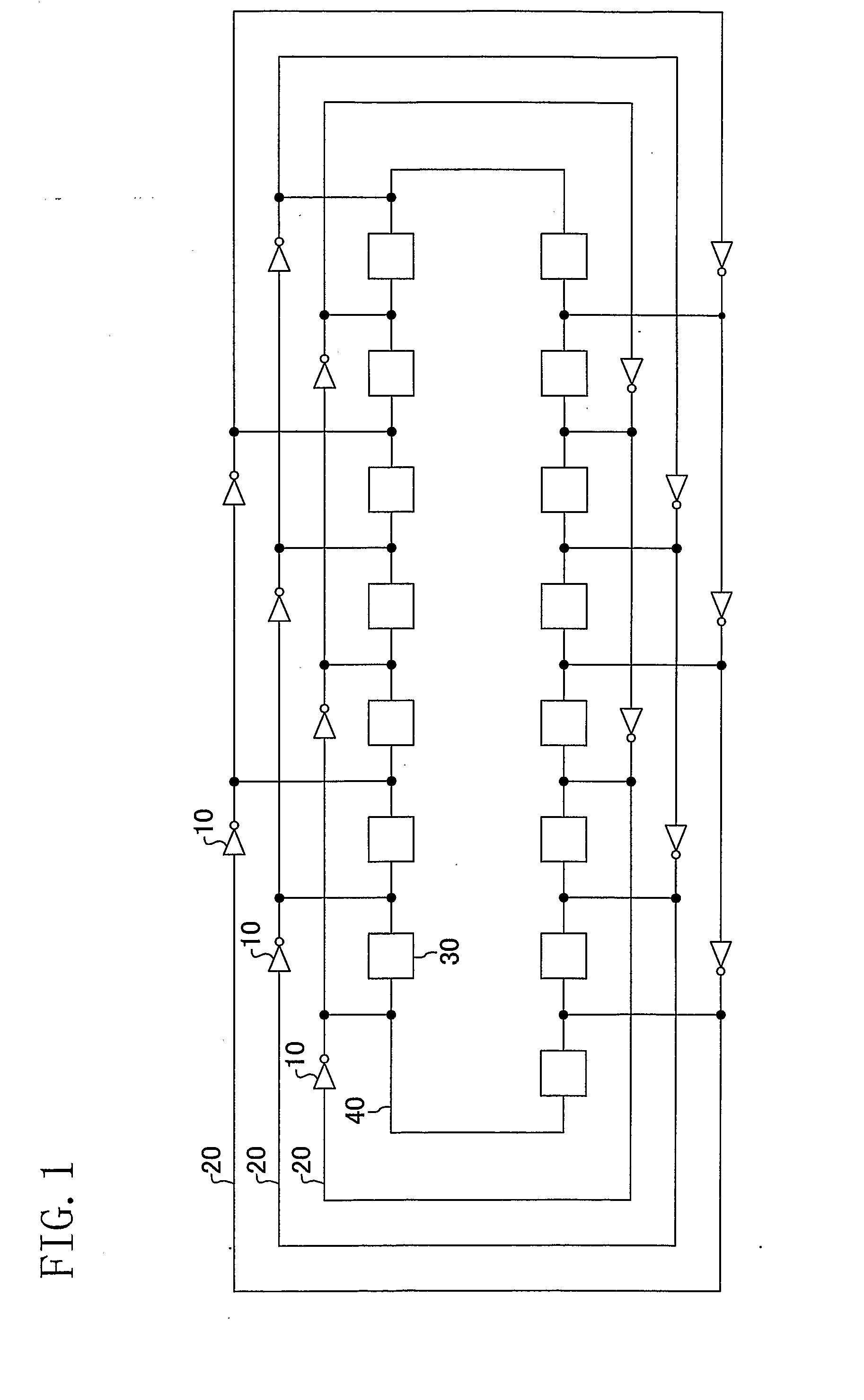
[0032]FIG. 1 shows the configuration of a coupled ring oscillator according to a first embodiment. The coupled ring oscillator shown in FIG. 1 includes three (n=3) ring oscillators 20, each composed of five (m=5) inverter circuits 10, and a phase-coupling loop 40 in which fifteen (m×n=15) phase-coupling circuits 30 are connected to form a loop.

[0033] The three ring oscillators 20 and the phase-coupling loop 40 are laid out in a nested pattern, in which the phase-coupling loop 40 is innermost. The connection points at which the phase-coupling circuits 30 are connected with each other and the connection points at which the inverter circuits 10 are connected with each other are connected. That is, the connection points of the phase-coupling circuits 30 and the connection points of the inverter circuits 10 are connected bijectively. Furthermore, each inverter circuit 10 is parallel-connected with three connected phase-coupling circuits 30. In other words, each inverter circuit 10 is co...

second embodiment

[0036]FIG. 3 shows the configuration of a coupled ring oscillator according to a second embodiment. As in the first embodiment, the coupled ring oscillator shown in FIG. 3 includes n(n=3) ring oscillators 20, each composed of five (m=5) inverter circuits 10, and a phase-coupling loop 40 in which fifteen (m×n=15) phase-coupling circuits 30 are connected to form a loop.

[0037] As in the first embodiment, the three ring oscillators 20 and the phase-coupling loop 40 are laid out in a nested pattern in which the phase-coupling loop 40 is innermost. The connection points of the phase-coupling circuits 30 and the connection points of the inverter circuits 10 are connected bijectively.

[0038] Unlike in the first embodiment, the phase-coupling circuits 30 of this embodiment each couple signal phases at two points in a common mode. That is, the phase-coupling circuits 30 are connected in such a manner that each phase-coupling circuit 30 connects two of the connection points of the inverter ci...


PUM


Abstract

A coupled ring oscillator includes n ring oscillators (20) each including m inverter circuits (10), and a phase-coupling loop (40) in which m×n phase-coupling circuits (30), each of which couples signal phases at two points in a certain phase mode, are connected with each other to form a loop. Connection points at which the inverter circuits (10) are connected with each other and the connection points at which the phase-coupling circuits (30) are connected with each other are connected bijectively; and each of the inverter circuits (10) is connected between two points that divide the phase-coupling circuits (30) into two parts at a certain ratio.

Description

TECHNICAL FIELD [0001] The present invention relates to ring oscillators and a method for laying out the ring oscillators, and more particularly relates to a coupled ring oscillator which uses a plurality of ring oscillators and is capable of generating highly accurate phase information and a method for laying out the coupled ring oscillator. BACKGROUND ART [0002] In order to record information on optical disc media such as a DVD (digital versatile disc), it is necessary to generate a special write-operation waveform for suppressing interference of a write signal. Generation of such a special write-operation waveform requires highly accurate phase information that is finer than one-fortieth of the write data rate. However, it is difficult to realize such extremely fine phase accuracy by a single inverter chain (a ring oscillator), because the phase delay thereof is shorter than a delay of a single inverter circuit. Therefore, conventionally, a plurality of ring oscillators are used ...

Claims


Application Information

Patent Timeline
IPC IPC(8): H03K3/03
CPCH03K3/0315
Inventor DOSHO, SHIROSAKIYAMA, SHIROTAKEDA, NORIAKI
Owner SOCIONEXT INC
Why Eureka
Try Eureka