
Image Processor

a processing program and image technology, applied in the field of image processors, can solve the problem that the method needs a lot of labor to construct a processing program, and achieve the effect of reducing the amount of labor required for constructing the processing program

Inactive Publication Date: 2008-03-20
NAT UNIV CORP YOKOHAMA NAT UNIV +1
View PDF5 Cites 30 Cited by
  • Summary
  • Abstract
  • Description
  • Claims
  • Application Information

AI Technical Summary

Benefits of technology

[0017] If an optical flow technique capable of extracting a moving direction or a moving distance of each point on a moving object from an image can be combined in the ACTIT method, it is expected that the optical flow technique effectively functions when an object which moves in the image can be extracted from a dynamic image, and it is expected that the precision of extraction is enhanced.
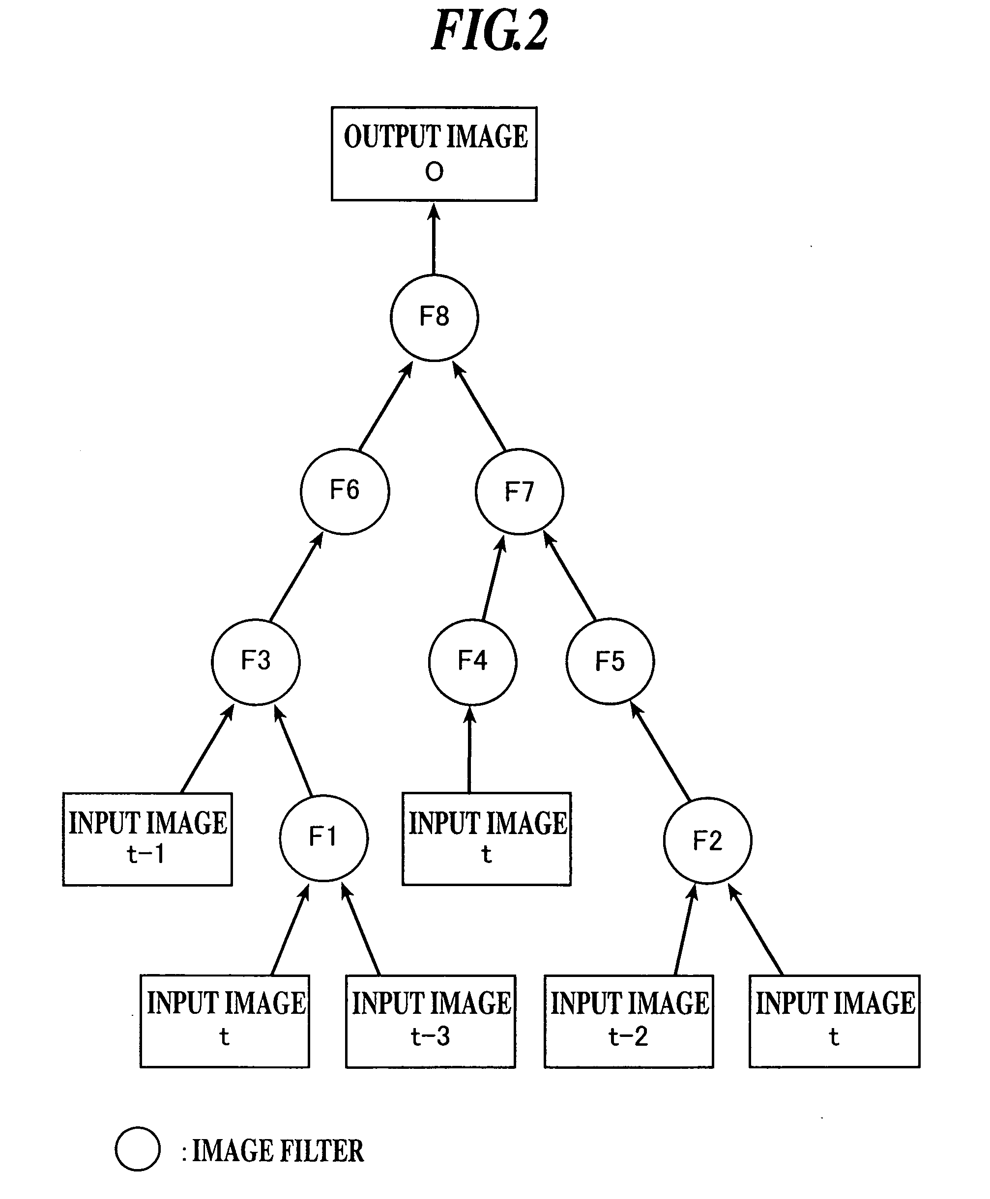
[0018] Hence, it is an object of the present invention to provide an image processor capable of expanding the image processing technique ACTIT so that the same image processing technique can be applied to a dynamic image, capable of extracting a specific object from the dynamic image based on a processing program comprising various image filters which are combined in a tree structure, and capable of extracting a specific object having time variation or displacement. It is also an object of the invention to provide a general image processor capable of easily obtaining such a processing program.
[0027] It is preferable that a fitness used for the genetic programming in the processing program forming section is calculated such that a value of the fitness is smaller as the number of nodes is greater.
[0029] It is preferable that a value of a fitness used for genetic programming in the processing program forming section is greater as the number of nodes of a two-input image filter in the processing program is greater.
[0048] Especially, as an image which is to be input to the processing program, the optical flow image produced from the plurality of images constituting the dynamic image is input. With this, a region on the image corresponding to the moving object indicative of peculiar flow in the dynamic image can be clearly pointed in the processing program. Thus, when a specific object extracted from the dynamic image is a moving object, the image processor of the present invention can reliably and precisely extract the moving object.

Problems solved by technology

However, these methods need much labor is usually required for constructing a processing program, and such processing program must be constructed for each of target specific object.

Method used


Image

  • Image Processor
  • Image Processor
  • Image Processor

Examples


first embodiment

[0101] In the embodiment, an image processor which is mounted on a vehicle and which extracts a pedestrian from a forward landscape image of a vehicle will be explained.

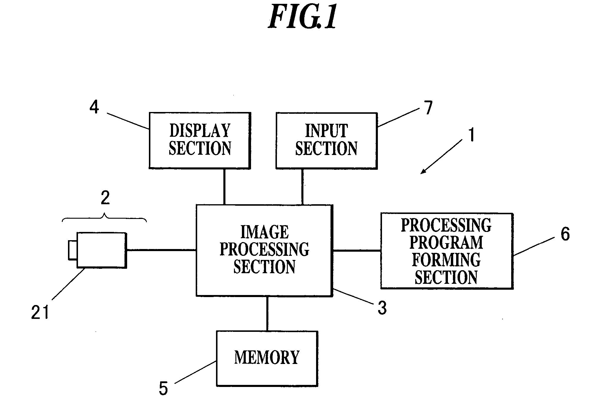
[0102]FIG. 1 is a block diagram showing a structure of the image processor of the embodiment. The image processor 1 includes an image input section 2, an image processing section 3, a display section 4, a memory 5, a processing program forming section 6 and an input section 7. In this embodiment, as the image processor 1, it is possible to use a computer comprising a CPU, a RAM, a ROM, an I / O interface which are connected to one another through buses.

[0103] The image input section 2 includes an imaging apparatus 21 capable of converting a picked up image into an electric signal. A CCD camera using a solid-state image sensing device such as a charge-coupled device (CCD) is used as the imaging apparatus 21. In this embodiment, the imaging apparatus 21 of the image input section 2 is mounted on an inner side of a fron...

second embodiment

[0181] A second embodiment of the image processor of the invention will be explained with reference to the drawings. In the second and third embodiments, image processors which are mounted on a vehicle for extracting an oncoming vehicle from a landscape image in front of the vehicle will be described, but the present invention is not limited to such image processors.

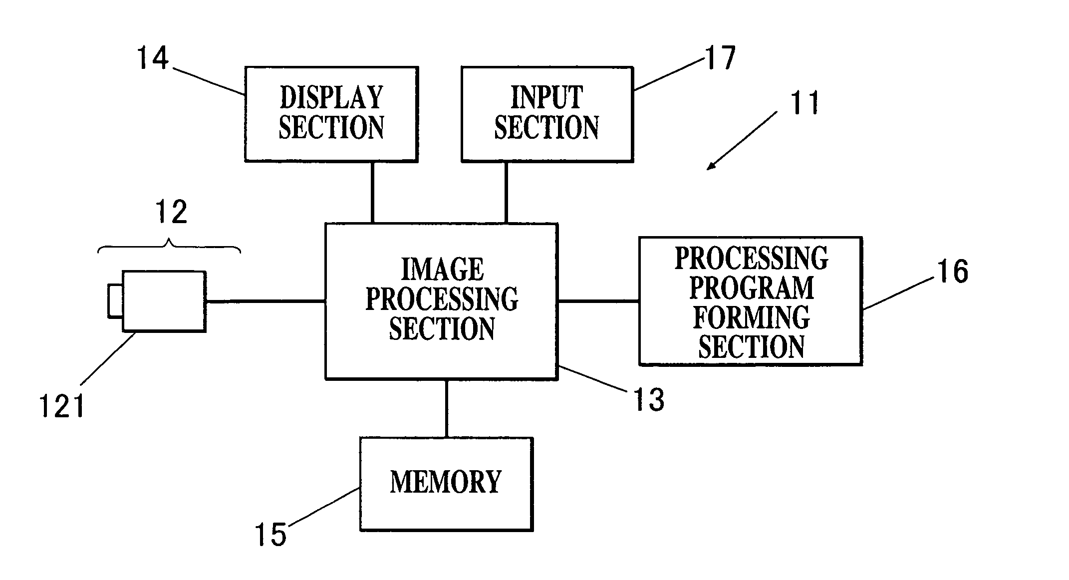
[0182]FIG. 18 is a block diagram showing a structure of the image processor of the embodiment. The image processor 11 includes an image input section 12, an image processing section 13, a display section 14, a memory 15, a processing program forming section 16 and an input section 17. As the image processor 11, it is possible to use a computer comprising a CPU, a RAM, a ROM, and an I / O interface in this embodiment.

[0183] Since the structure of the image input section 12 is the same as the image input section 2 of the first embodiment, explanation thereof will be omitted. An image signal which is output from an imaging ...

third embodiment

[0238] The third embodiment is different from the second embodiment in that an image after the conversion processing is input as input images t, t−1, . . . , t−k to be input to the processing program, instead of inputting a picked up image of a front landscape of the subject vehicle picked up by the imaging apparatus 21 as described in the second embodiment as it is or inputting a compressed image.

[0239] Therefore, in this embodiment, the optical flow image is also produced based on the input images t, t−1 after the conversion processing and is input to the processing program. Images corresponding to the input images t, t−1 after the conversion processing are used as a target image T and a weight image W used when forming a processing program BP which is optimized using the genetic programming technique by the processing program forming section 16.

[0240] In this embodiment, an input image after the conversion processing is called a converted image. Structures of the image processo...


PUM


Abstract

An image processor (1) for subjecting an image picked up by an imaging apparatus (21) to image processing to extract a specific object from the image, the image processor comprising: an image processing section (3) which subjects a plurality kinds of images (t, t−1, . . . , t−k) picked up by the imaging apparatus to the image processing based on a processing program comprising image filters (F) combined in a form of a tree structure, and which forms an output image (O) in which the specific object is extracted.

Description

TECHNICAL FIELD [0001] The present invention relates to an image processor, and more particularly, to an image processor capable of extracting a specific object from an image. BACKGROUND ART [0002] In recent years, researches of an image processor and an image processing method are heavily conducted for picking up a subject or a landscape by means of image inputting means such as a TV camera and a CCD camera, and subjecting the obtained dynamic image to image processing, thereby extracting a specific object, e.g., an object moving in an environment or the movement from the image (e.g., see patent documents 1 to 5). [0003] In a field of an automobile, such an image processor is used for picking up a forward landscape by a CCD camera or the like mounted on a vehicle to extract a pedestrian or other vehicle from the dynamic image, thereby avoiding an accident such as collision against it (see the patent documents 1 to 3). In a filed of an artificial intelligent robot, the image process...

Claims


Application Information

Patent Timeline
Patent Type & Authority Applications(United States)
IPC IPC(8): G06K9/00
CPCG06T7/2006G06T2207/30261G06T2207/20144G06T2207/10016G06T7/215G06T7/194
Inventor NAGAO, TOMOHARUYOKOI, WATARUOGAWA, GENYAKISE, KATSUYUKITORII, TSUYOSHI
Owner NAT UNIV CORP YOKOHAMA NAT UNIV
Learn More