
Separator and Non-Aqueous Electrolyte Secondary Battery Using Same

a secondary battery and electrolyte technology, applied in the field of separators, can solve the problems of poor charge/discharge characteristics of batteries, impaired charge/discharge characteristics of high-rate batteries, and inability to charge/discharge in low-temperature environments, etc., to achieve high discharge capability, improve safety, and improve the effect of performan

Inactive Publication Date: 2008-03-20
PANASONIC CORP
View PDF10 Cites 95 Cited by
  • Summary
  • Abstract
  • Description
  • Claims
  • Application Information

AI Technical Summary

Benefits of technology

[0031] According to the present invention, it is possible to provide a non-aqueous electrolyte secondary battery having improved safety, high performance and large current discharge capability particularly at low temperatures.

Problems solved by technology

Although the use of a separator having a layer including inorganic particles as a filler that functions to prevent the heat shrinkage can improve the safety of the battery particularly in the event of an internal short-circuit as in a nail penetration test, the battery tends to exhibit poor charge / discharge characteristics.
This has been an important practical issue.
As a result, high rate charge / discharge characteristics are impaired, and charge / discharge in a low temperature environment may not be performed.

Method used


Image

  • Separator and Non-Aqueous Electrolyte Secondary Battery Using Same
  • Separator and Non-Aqueous Electrolyte Secondary Battery Using Same
  • Separator and Non-Aqueous Electrolyte Secondary Battery Using Same

Examples


example

[0077] The following describes examples of the present invention, but it should be understood that the examples given below are merely illustrative and the scope of the present invention is not limited thereto.

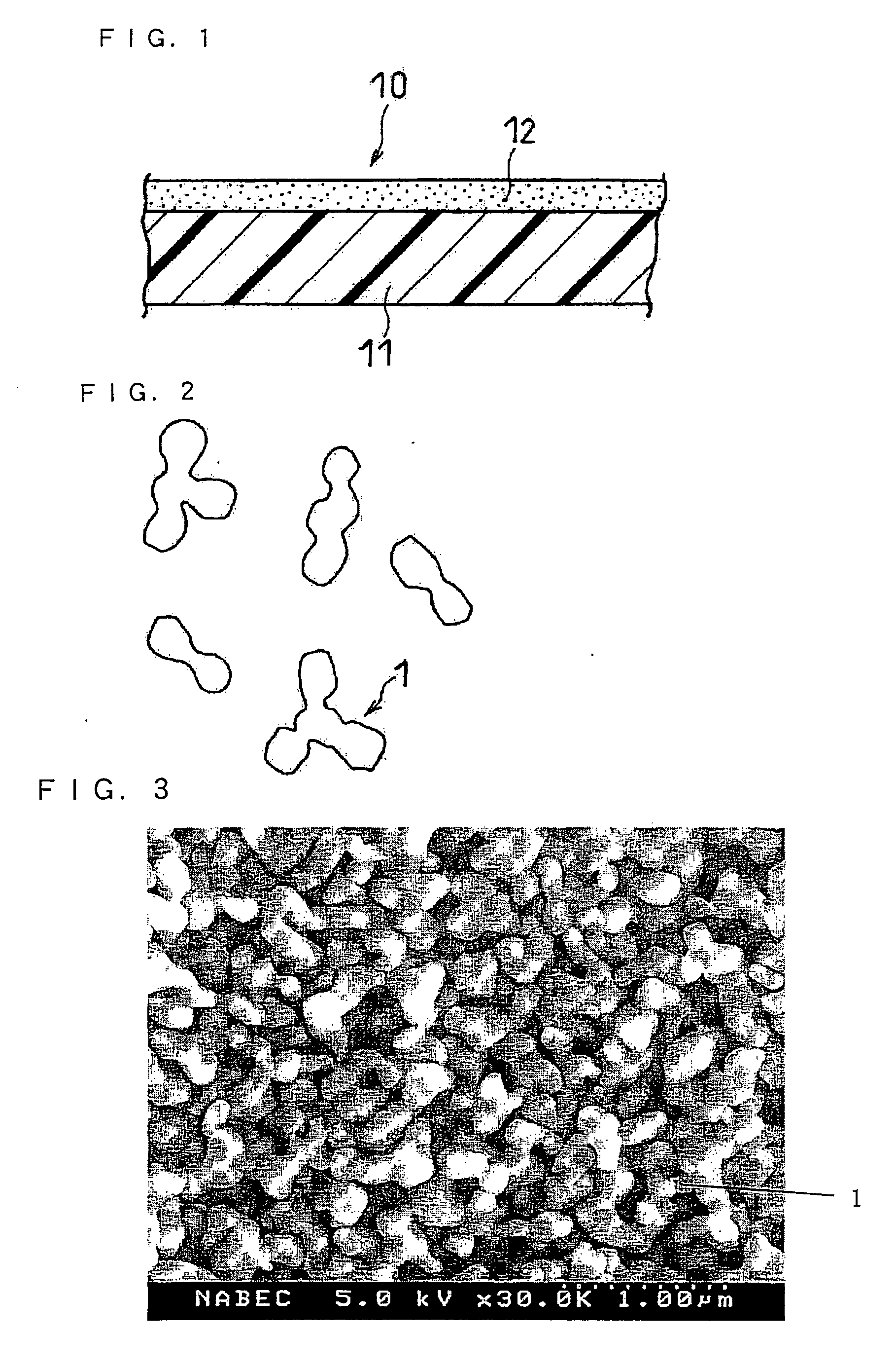
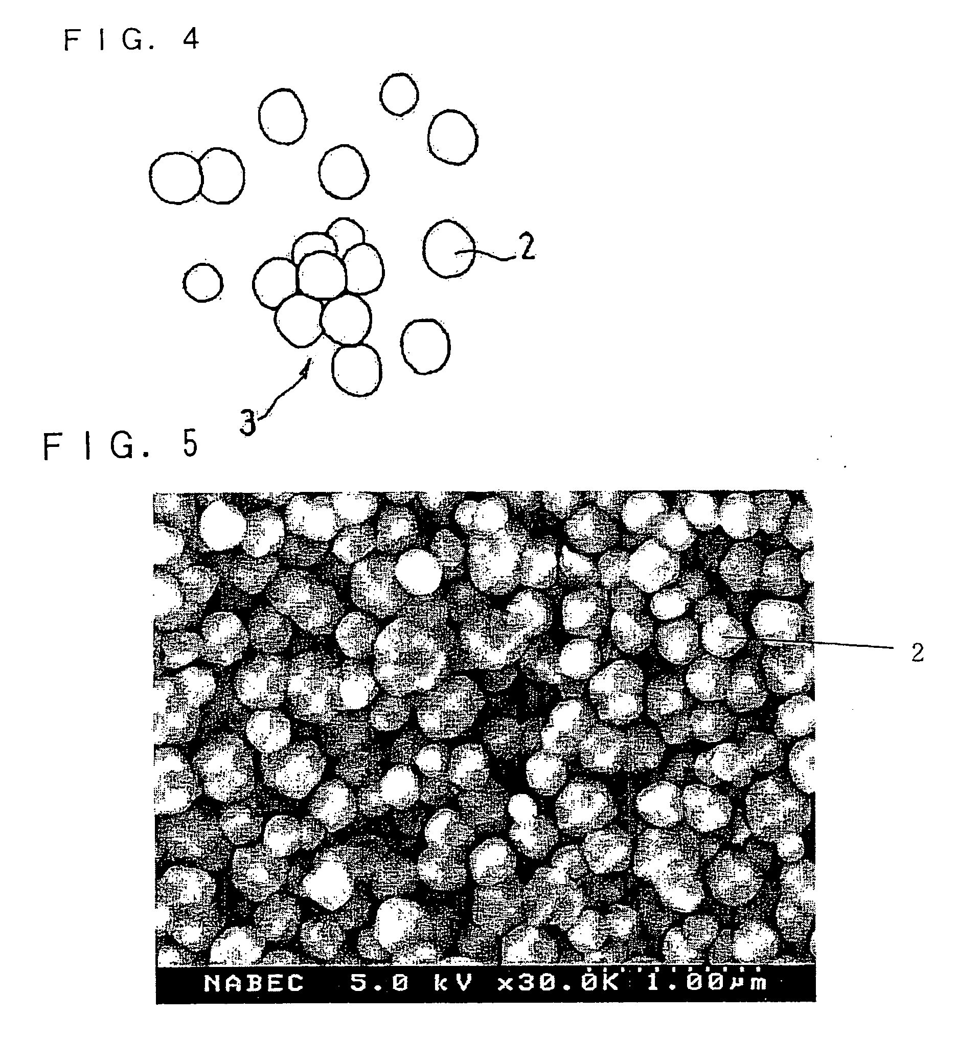
[0078] A raw material powder of alumina (primary particles) having an average particle size of 0.1 μm was sintered at 1100° C. for 20 minutes, which was then sized using a wet type ball mill having 15 mm diameter alumina balls therein. Thereby, a joined-particle filler having an average particle size of 0.5 μm was obtained. This filler in an amount of 100 parts by weight was mixed with 4 parts by weight of a polyacrylic acid derivative (MB-720H available from Zeon Corporation, Japan) as a binder and N-methyl-2-pyrrolidone (NMP) as a solvent, which was then adjusted to have a nonvolatile content of 60 wt % using a stirrer. The resultant was dispersed in a bead mill having an internal volume of 0.6 L, 80% of which was filled with 0.2 mm diameter zirconia beads. Thereby, a paste...

examples 1 to 7

[0113] A lithium ion secondary battery was prepared in the same manner as described above using the paste A1 as a paste for forming the fine particulate filler-containing layer. This battery was referred to as a test battery of Example 1.

[0114] Likewise, lithium ion secondary batteries were produced in the same manner as in Example 1 except that the pastes A2, A3, A4, A5, A6 and A7 were used as pastes for forming the fine particular filler layer. These batteries were referred to as batteries of Examples 2, 3, 4, 5, 6 and 7, respectively.

example 8

[0122] A paste for forming the fine particulate filler-containing layer was prepared in the same manner as the paste A1 was prepared except that the amount of the binder (i.e., polyacrylic acid derivative (MB-720H available from Zeon Corporation, Japan)) was changed to 1 part by weight per 100 parts by weight of the joined-particle filler. Then, a lithium ion secondary battery was produced in the same manner as in Example 1 except that the paste prepared above was used.


PUM


Abstract

A separator including at least a layer containing a fine particulate filler and a shutdown layer. The fine particulate filler includes a joined-particle filler that is in the form of a plurality of primary particles joined and bonded to one another. A non-aqueous electrolyte secondary battery including this separator exhibits improved safety, high performance and large current discharge capability particularly at low temperatures.

Description

TECHNICAL FIELD [0001] The present invention relates to a non-aqueous electrolyte secondary battery, and more particularly to a separator therefor. More specifically, this invention relates to an improved separator to achieve a high performance non-aqueous electrolyte secondary battery having enhanced safety and to a non-aqueous electrolyte secondary battery comprising the separator. BACKGROUND ART [0002] In general, secondary batteries (electrochemical batteries) such as lithium ion secondary batteries include an electrode group comprising a positive electrode, a negative electrode and a separator for electrically insulating the positive and negative electrodes from each other and for retaining electrolyte. [0003] The separator functions to prevent a short-circuit between the positive and negative electrodes during normal operation so as to ensure safety of the battery. Separators for use in non-aqueous electrolyte secondary batteries have a special function. Particularly, separato...

Claims


Application Information

Patent Timeline
IPC IPC(8): H01M2/16H01M10/05H01M10/36H01M50/443H01M50/449H01M50/451H01M50/489
CPCH01M2/164H01M10/05H01M2/1686H01M2/166Y02E60/10H01M50/446H01M50/449H01M50/451H01M50/443H01M50/489H01M50/574H01M50/403H01M50/431H01M50/414H01M10/0525
Inventor KASAMATSU, SHINJISHIMADA, MIKINARI
Owner PANASONIC CORP
Learn More