Compression Device, System and Method of Use

a compression device and compression technology, applied in the field of compression therapy, can solve the problems of affecting the blood flow of the limb, affecting the care of patients, and causing nuisance or safety hazards for caregivers, and achieve the effect of improving the blood flow in the limb

Active Publication Date: 2008-03-20
KPR U S LLC
View PDF56 Cites 42 Cited by
  • Summary
  • Abstract
  • Description
  • Claims
  • Application Information

AI Technical Summary

Benefits of technology

[0004]In general, a compression device of this invention is used for cyclically compressing the limb of a patient to improve blood flow in the limb. The compression device comprises a compressive section sized and shaped for extending generally circumferentially around a portion of the limb for applying compressive pressure to the limb portion, and a housing operatively connected to the compressive section. The housing includes first and second housing members movable relative to each other between a contracted position in which the housing has a first dimension for relaxing pressure on the limb portion, and an expanded position in which the housing has a second dimension greater than the first dimension for compressing the limb portion. A non-pneumatic mechanical actuator is provided in the housing for cyclically moving the first and second housing members from their contracted position to their expanded position.

Problems solved by technology

In addition, while the device is on the patient, it is possible that tubes become entangled in the patient's limbs and / or become a nuisance or safety hazard to caregivers and visitors who may be close to the bed.

Method used


Image

  • Compression Device, System and Method of Use
  • Compression Device, System and Method of Use
  • Compression Device, System and Method of Use

Examples


first embodiment

[0077]As explained in regard to the first embodiment, more than one compression device 501 can be used to sequentially compress different portions of the same limb (e.g., one leg) or different limbs (e.g., two legs). If more than one device 501 is used, the VRT is determined separately for each limb portion being compressed. Preferably, the longest of the measured vascular refill times is then used as the new relax interval for all of the compression devices. The VRT measurements for the compression devices are made (i.e., started and stopped) independent of one another. Preferably, however, any adjustment to the relax interval of the compression devices is not made until after the VRT measurements have been completed for all devices.

[0078]As an enhanced safety feature, the control system 201 of the compression system 501 may provide an audible and / or visual error alarm for one or more of the following error conditions: high pressure error, including a sensed pressure greater than a...

fourth embodiment

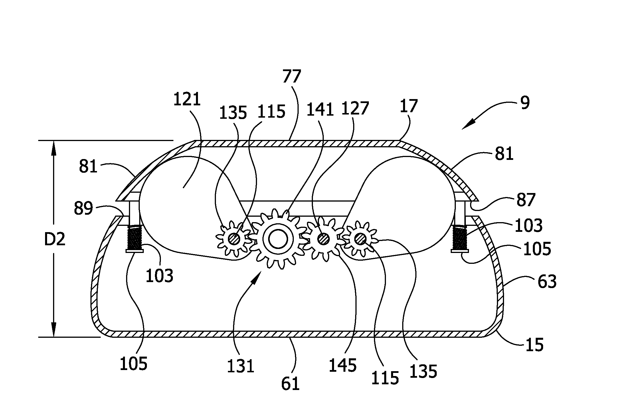
[0083]FIG. 14 illustrates a compression device of this invention, generally designated 701. This embodiment is similar to the compression device 501 previously described in that it comprises a compressive section 707 adapted to extend around a portion 709 of a limb, at least one pneumatic bladder 715, and a non-pneumatic mechanical device, generally designated 719. The bladder(s) 715 and mechanical device 719 combine to form a module 721 which is received (e.g., removably received) in a pocket 723 on the compressive section 707. The module 721 may be operatively connected to the compressive section 707 in other ways. As described below, the module 721 is adapted for cyclic expansion and contraction in opposite generally radial directions 724 with respect to the limb portion 709 between a contracted condition in which the module has a first dimension 761 for relaxing pressure on the limb portion, and an expanded condition (FIG. 14A) in which the module has a second dimension 763 grea...


PUM


Abstract

Apparatus and methods for cyclically compressing the limb of a patient to improve blood flow in the limb. In one embodiment, a compression device includes a compressive section sized and shaped for extending around a portion of the limb for applying compressive pressure and a housing operatively connected to the compressive section. The housing includes first and second housing members movable relative to each other between contracted and expanded positions. A non-pneumatic mechanical actuator is provided in the housing for cyclically moving the first and second housing members from their contracted position to their expanded position.

Description

BACKGROUND OF THE INVENTION[0001]This invention relates generally to compression therapy, and more particularly to devices which enhance blood flow to avoid circulation problems, such as deep vein thrombosis (DVT).[0002]Cyclical compression of a body part (e.g., leg) is beneficial to a person who has a blood circulation problem involving poor venous return to the heart. Many devices on the market and in the prior art provide compression by using one or more pneumatic bladders that encircle the leg or other limb(s). The bladders are inflated in a predetermined sequence and to a prescribed pressure at timed intervals. The device that controls the inflation typically employs an air pump or compressor and a number of valves that operate to direct the flow of air to the bladders. Conventional products use a bladder-filled sleeve wrapped around the limb and a tube that connects the bladder(s) to a controller device that resides separately from the patient such as on the footboard of a bed...

Claims


Application Information

Patent Timeline
Patent Type & Authority Applications(United States)
IPC IPC(8): A61H19/00A61H7/00
CPCA61B5/024A61B5/026A61B5/6824A61B5/6828A61H23/02A61B17/1325A61B17/1355A61H11/00A61B5/6829
Inventor NARDI, STEVEDENSON, JESSE E.WUDYKA, SCOTTBOCK, MALCOLM
Owner KPR U S LLC
Why Eureka
Try Eureka