Turbomachine fan duct

a technology for turbomachines and fan ducts, which is applied in the direction of machines/engines, liquid fuel engines, power plant inspection panels, etc., can solve the problems of relative short downtime of airplanes fitted with turbomachines, and achieve the effect of simple, effective and economical solution

Active Publication Date: 2008-03-27
SN DETUDE & DE CONSTR DE MOTEURS DAVIATION S N E C M A
View PDF9 Cites 27 Cited by
  • Summary
  • Abstract
  • Description
  • Claims
  • Application Information

AI Technical Summary

Benefits of technology

[0009] It is a particular object of the invention to afford a simple, effective and economical solution to these problems.

Problems solved by technology

They therefore result in relatively short down-times for the airplane fitted with the turbomachine.

Method used


Image

  • Turbomachine fan duct
  • Turbomachine fan duct
  • Turbomachine fan duct

Examples


Embodiment Construction

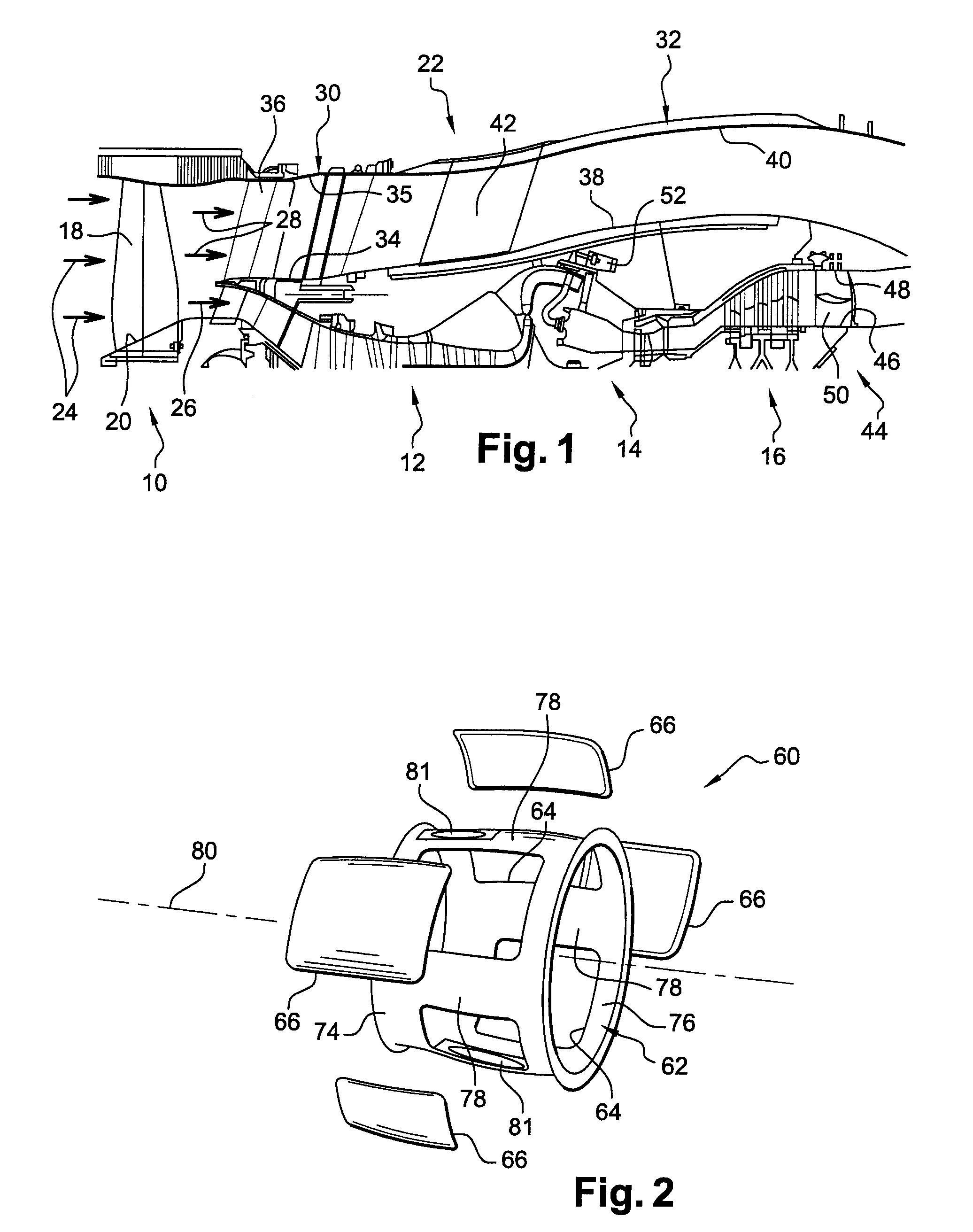
[0030]FIG. 1 schematically depicts a bypass turbojet comprising, from the upstream end downstream, in the direction in which the gases flow within the turbojet, a fan 10, a compressor 12, a combustion chamber 14 and turbines 16, this turbojet being intended to be attached by appropriate means under a wing of an airplane or to the rear part of the fuselage of an airplane.

[0031] The fan 10 comprises a plurality of blades 18 which are fixed at their radially internal ends to the periphery of the fan disk 20 of the turbojet secured to the upstream end of a shaft (not depicted) of the turbojet. The fan blades 18 are externally surrounded by a retaining case mounted at the upstream end of the nacelle 22 of the turbojet which is substantially cylindrical and extends in the downstream direction around the compressor 12, the combustion chamber 14 and the turbines 16 of the turbojet.

[0032] This nacelle 22 ducts the air stream 24 entering the turbojet. Some 26 of this air stream, which forms...


PUM


Abstract

Turbomachine fan duct comprising two coaxial cylindrical walls (60, 68), these being an internal wall and an external wall, respectively, the internal wall (68) consisting of a framework (70) to which panels (72) are removably attached, and the external wall (60) consisting of a single support structure (62) comprising openings (64) closed by removable panels (66), the openings (64) in the external wall having dimensions that allow the panels (72) of the internal wall to pass and allow these panels to be fitted onto and removed from the framework (70) of the internal wall.

Description

BACKGROUND OF THE INVENTION [0001] The present invention relates to a fan duct for a turbomachine such as an airplane turbojet. [0002] The fan duct of a turbomachine forms part of the nacelle and extends around the turbomachine engine, between the fan and the jet pipe. [0003] It comprises two substantially cylindrical walls which run one inside the other and between them delimit an annular space through which some of the air sucked in by the fan, called the cold stream or the bypass air stream, can flow. The rest of the air sucked in by the fan enters the engine of the turbomachine which, from the upstream end downstream, comprises a compressor, a combustion chamber and a turbine, and forms the hot air stream or primary air stream. [0004] The internal wall of the duct is attached at its upstream end to an intermediate case of the turbomachine and is connected at its downstream end to an exhaust case. It is shaped in such a way as to envelope the turbomachine engine from a short radi...

Claims


Application Information

Patent Timeline
Patent Type & Authority Applications(United States)
IPC IPC(8): F02K5/00F04D29/44
CPCB64D29/08F01D25/24F05D2240/14Y02T50/672F05D2230/60F02K3/06Y02T50/60
Inventor BEUTIN, BRUNO ALBERTDERENES, JACKY RAPHAEL MICHEL
Owner SN DETUDE & DE CONSTR DE MOTEURS DAVIATION S N E C M A
Why Eureka
Try Eureka