Artificial lateral line

Active Publication Date: 2008-03-27
THE BOARD OF TRUSTEES OF THE UNIV OF ILLINOIS
View PDF37 Cites 22 Cited by
  • Summary
  • Abstract
  • Description
  • Claims
  • Application Information

AI Technical Summary

Problems solved by technology

The spatial and temporal evolution of surface flow features is extremely difficult to obtain due to limitations of c

Method used


Image

  • Artificial lateral line
  • Artificial lateral line
  • Artificial lateral line

Examples


Embodiment Construction

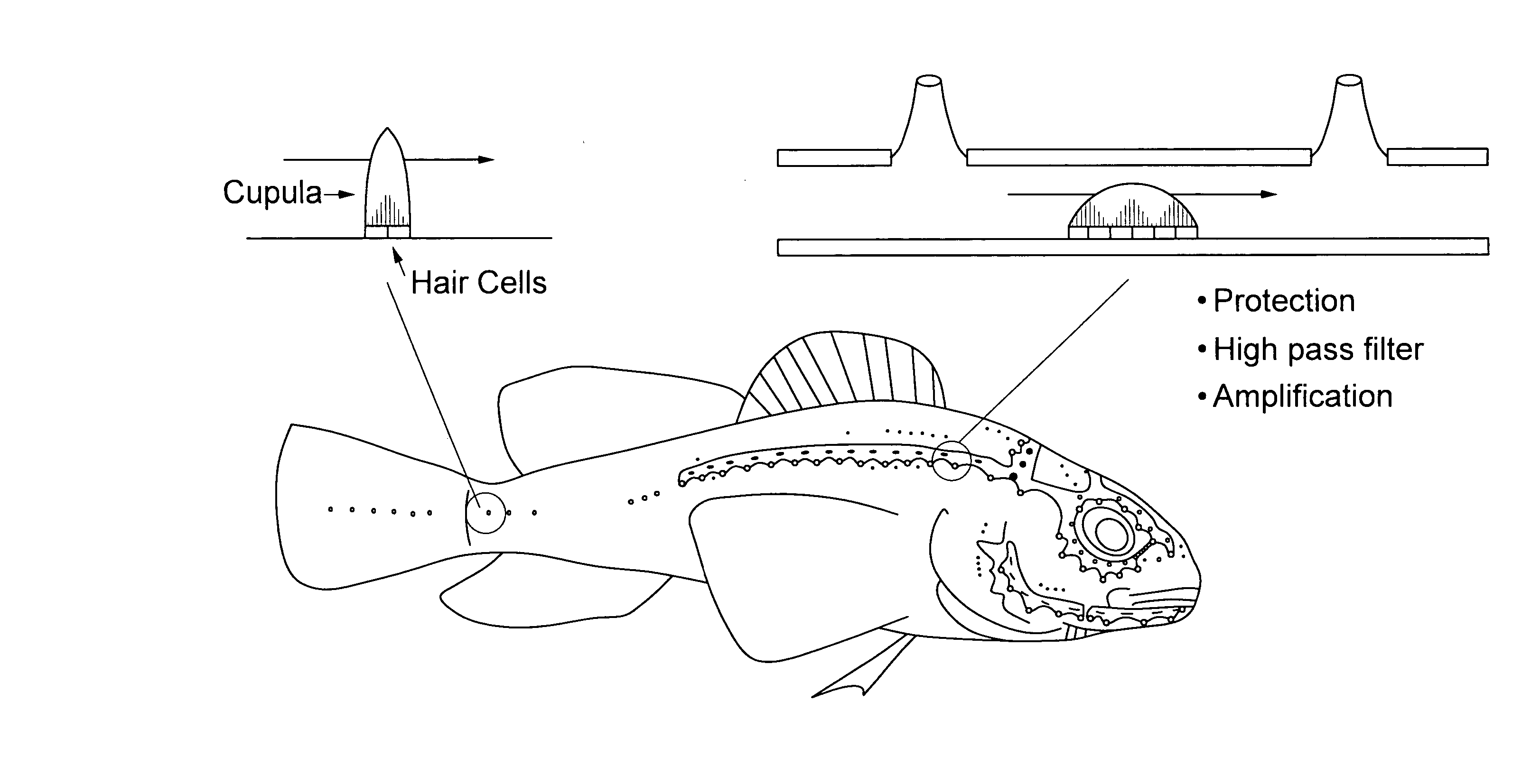
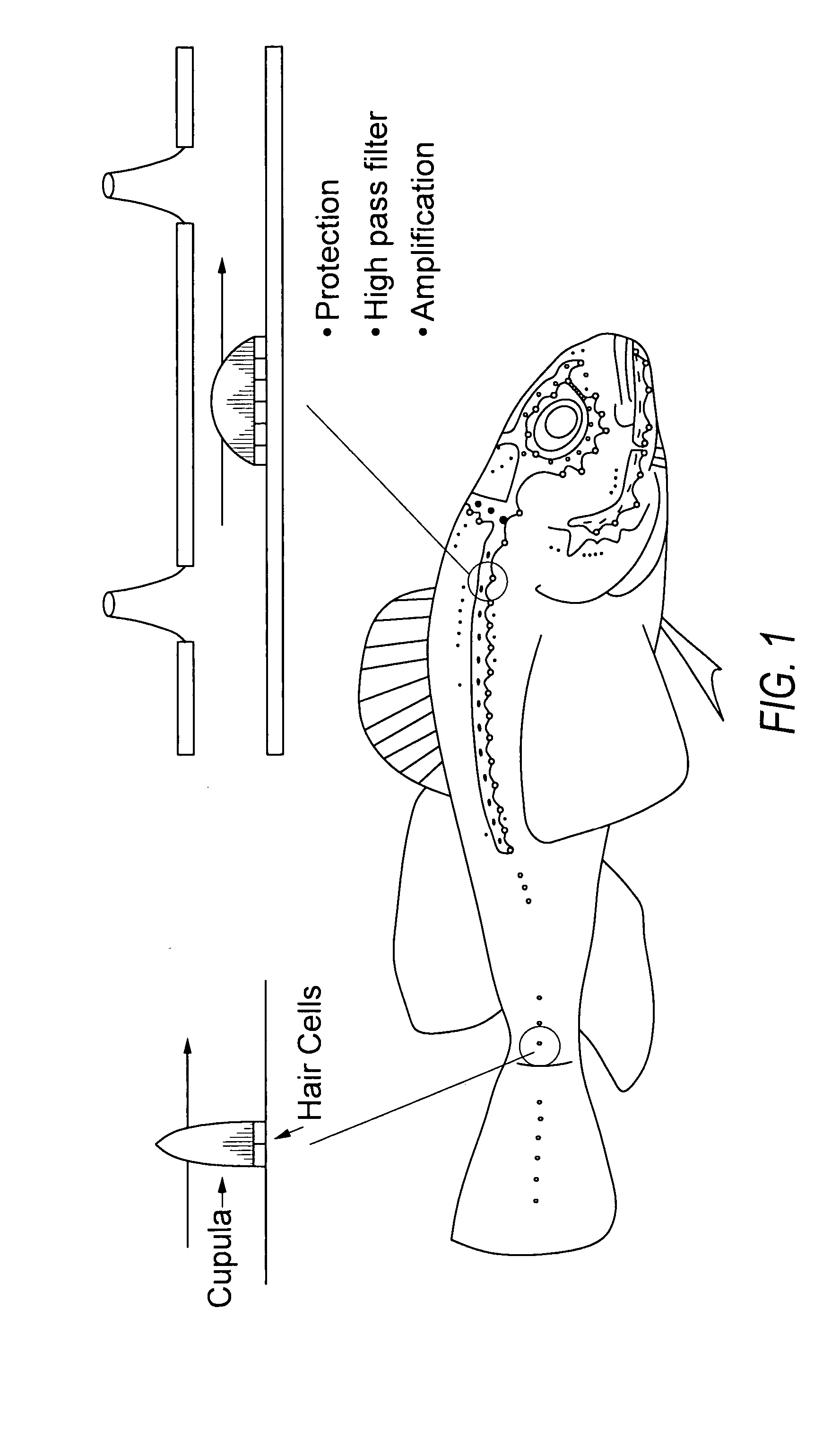
[0035] Fish and many underwater animals utilize multimodal sensitive skin that can detect flow, pressure distribution, electrical potential and field, and local vortex. In nature, a lateral line is a spatially distributed system of flow sensors found on the body surface of fish and aquatic amphibians. A lateral line, for example, usually spans the length of the fish's body. Lateral lines form spatial-temporal images (AC, DC) of nearby sources based on the sources' hydrodynamic signatures.

[0036] For example, linearly distributed along the lateral line of fish are clustered sensor hair cell bundles embedded in a gel-like dome called neuromasts, each capable of sensing local flow velocity. Neuromasts can be classified into two types: superficial neuromasts, as shown in FIG. 1 (left), and canal neuromasts, as shown in FIG. 1 (right). A superficial neuromast is situated on the surface of the fish and responds in proportion to fluid velocity. By contrast, a canal neuromast is packaged in...


PUM


Abstract

An artificial sensor comprises at least one substrate, and a plurality of flow sensors disposed on the at least one substrate for providing a plurality of spatial-temporally varying signals representing a hydrodynamic stimulus. The plurality of flow sensors are spatially distributed on the at least one substrate. A processor is coupled to the plurality of flow sensors for receiving the signals and determining spatial-temporal information from the received signals.

Description

PRIORITY CLAIM [0001] This application is a continuation-in-part of pending U.S. patent application Ser. No. 10 / 861,096, filed Jun. 4, 2004. This application claims the benefit of U.S. Provisional Patent Application Ser. No. 60 / 817,885, filed Jun. 30, 2006, under 35 U.S.C. § 119.STATEMENT OF GOVERNMENT INTEREST [0002] This invention was made with Government assistance under Air Force Office of Scientific Research (AFOSR) Grant No. FA9550-05-1-0459. The Government has certain rights in the invention.FIELD OF THE INVENTION [0003] This application relates generally to the field of artificial sensors. BACKGROUND OF THE INVENTION [0004] Comprehensive flow sensing involves measurement of, for example, pressure, shear stress (drag and vortex), temperature, and three-axis flow rates. The spatial and temporal evolution of surface flow features is extremely difficult to obtain due to limitations of convention scientific instruments. Conventional flow sensing instruments are singular point mea...

Claims


Application Information

Patent Timeline
IPC IPC(8): G01L7/00
CPCG01F1/28G01F1/6845G01K7/015G01K7/186G01N13/00G01N2203/0676G01P5/02G01P5/12G01L5/228
Inventor LIU, CHANGENGEL, JONATHANCHEN, JACK
Owner THE BOARD OF TRUSTEES OF THE UNIV OF ILLINOIS
Why Eureka
Try Eureka