Liquid Conservation Device and a Liquid Apparatus Incorporating the Liquid Conservation Device

a technology of liquid conservation device and liquid apparatus, which is applied in the direction of water supply installation, heating type, functional valve type, etc., can solve the problems of water loss down the drain, water supply becoming more and more scarce,

Inactive Publication Date: 2008-03-27
WATER MISER AUST
View PDF4 Cites 22 Cited by
  • Summary
  • Abstract
  • Description
  • Claims
  • Application Information

AI Technical Summary

Benefits of technology

[0015] The housing may define a shuttle chamber, and the primary valve may be a shuttle valve that ...

Problems solved by technology

This therefore leads to a loss of this water down a drain.
This is particularly ...

Method used


Image

  • Liquid Conservation Device and a Liquid Apparatus Incorporating the Liquid Conservation Device
  • Liquid Conservation Device and a Liquid Apparatus Incorporating the Liquid Conservation Device
  • Liquid Conservation Device and a Liquid Apparatus Incorporating the Liquid Conservation Device

Examples


first embodiment

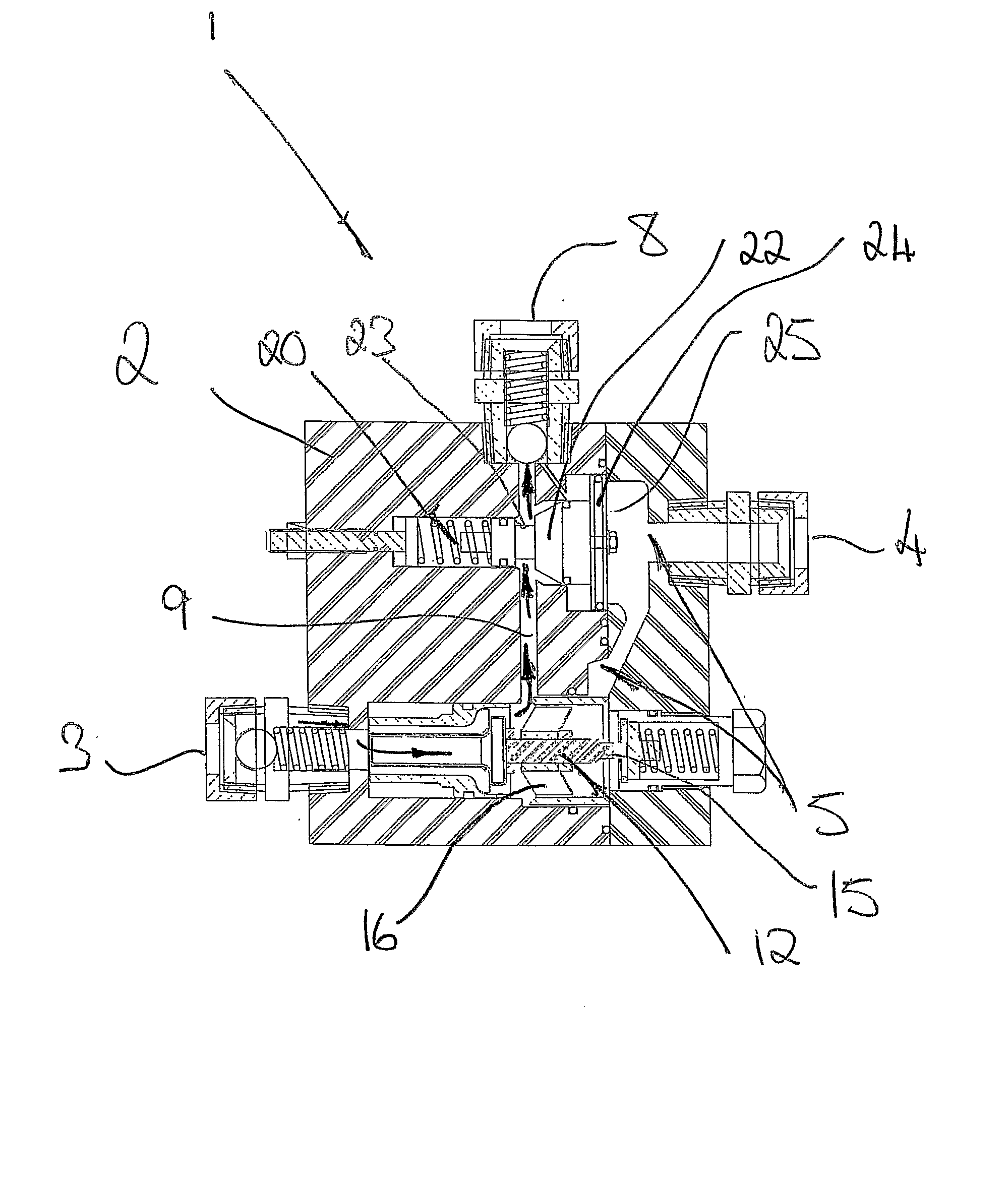
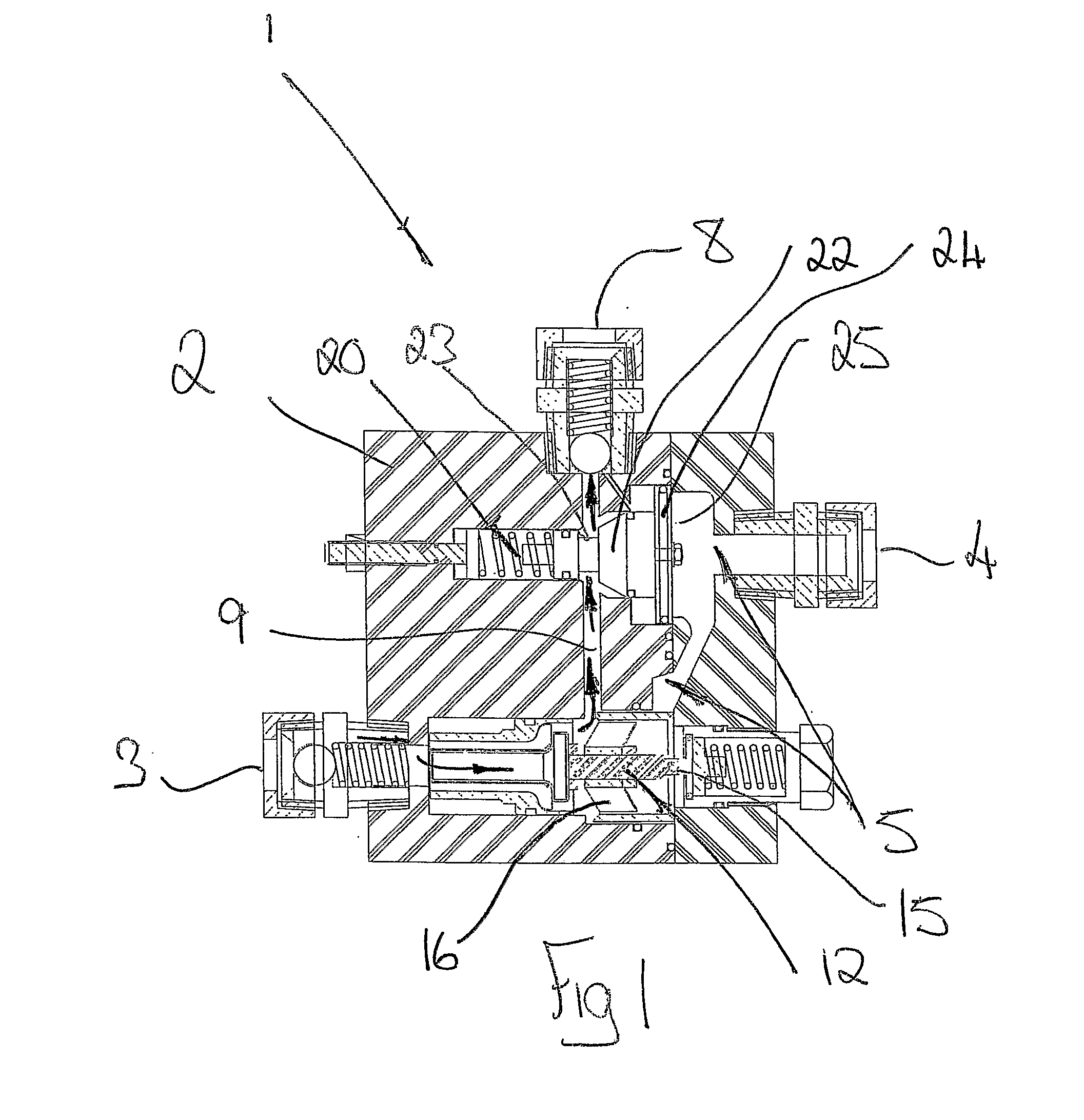
[0050]FIG. 1 is a schematic cross-sectional view of the device in accordance with the invention with the shuttle valve in a diverting position directing water into the secondary flow passage and the secondary valve in an open position;

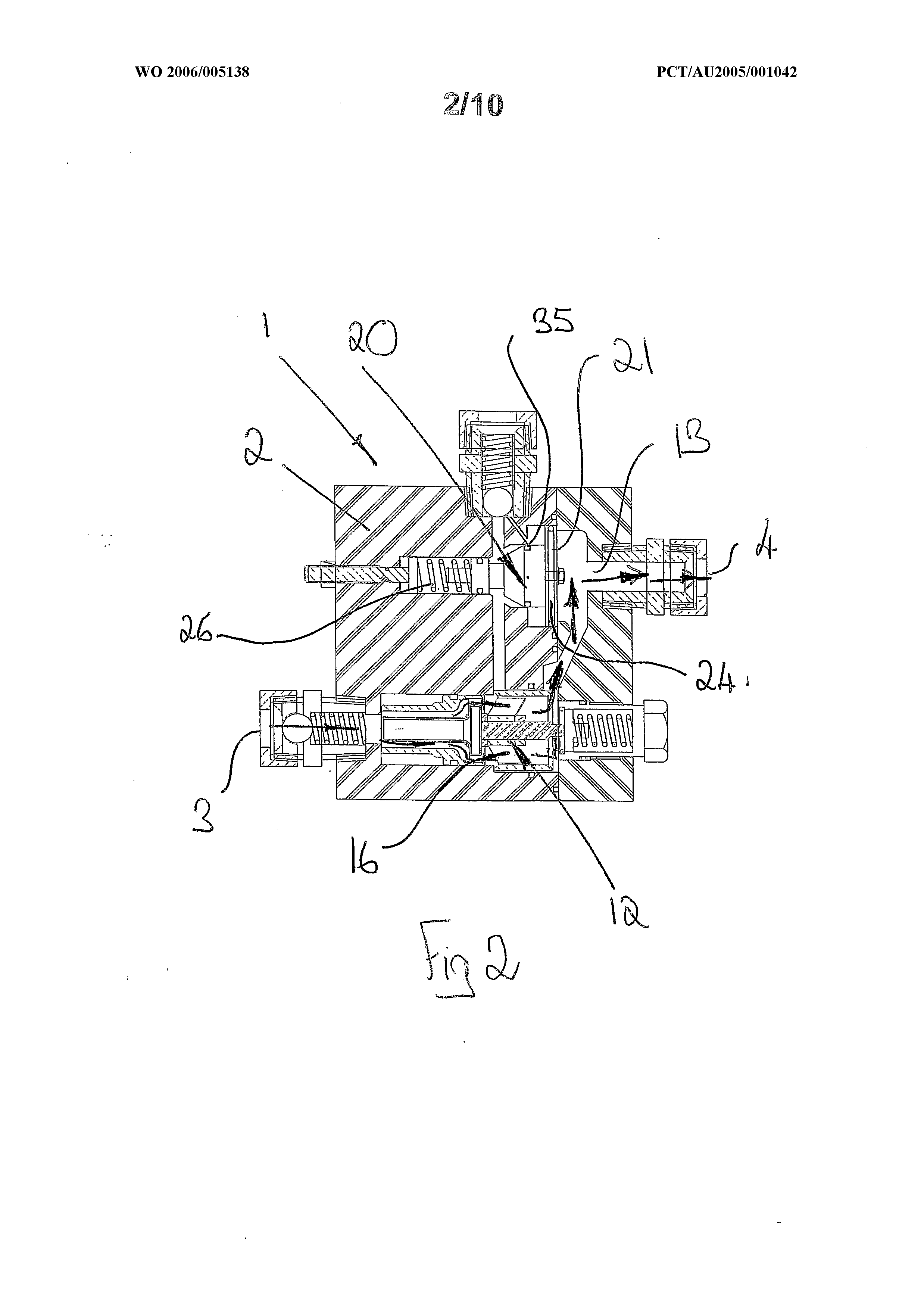
[0051]FIG. 2 shows the device of FIG. 1 with the shuttle valve in a normal operating position directing water through the downstream portion of the primary flow passage and shutting off flow through the secondary flow passage and the secondary valve in the open position;

[0052]FIG. 3 shows the device of FIG. 1 with the shuttle valve in the normal operating position and the secondary valve moved to the closed position due to a tap adjacent to the device being switched off;

[0053]FIG. 4 shows the device of FIG. I after some period of non use with the shuttle valve having moved back to the diverting position and the secondary valve still in the closed position;

[0054]FIG. 5 is a schematic flow sheet showing how the device might be used in a domestic hot w...

second embodiment

[0055]FIG. 6 is an exploded three dimensional view of a device in accordance with the invention;

[0056]FIG. 7 is an end view of the device of FIG. 6;

[0057]FIG. 8 is a three dimensional view of one of the components of the shuttle valve assembly of the device of FIG. 6;

[0058]FIG. 9 is a three dimensional view of another one of the components of the shuttle valve assembly of the device of FIG. 6;

[0059]FIG. 10 is a sectional view of one component making up the housing of the device of FIG. 6, section through X-X, the component rotated through 180 degrees about its longitudinal axis when compared with its orientation shown in FIG. 6;

[0060]FIG. 11 is an end view of the component shown in FIG. 10;

[0061]FIG. 12 is a sectional view of the device in FIG. 6, section taken through XII-XII, wherein the shuttle valve is in a diverting position and the secondary valve is in an open position; and

[0062]FIG. 13 is a further sectional view of the device in FIG. 12, wherein the shuttle valve is i...


PUM


Abstract

A water saving device for us in a hot water system to recover an initial volume of cold water when a hot water tap is turned on. The device has an inlet for receiving water piped from a water heater, a primary outlet for delivering hot water to a tap, and a by-pass outlet through which any cooled water is diverted by a thermally actuated shuttle valve. The device also includes a secondary valve for closing off the by-pass outlet when the water pressure downstream of the primary outlet is high (such as when the down stream hot water delivery tap is closed and opening the by pass outlet when the water pressure downstream of the primary outlet is low, such as when the downstream hot water delivery tap is opened.

Description

FIELD OF THE INVENTION [0001] This invention relates to a liquid conservation device. The invention also extends to a liquid conservation apparatus including the conservation device. [0002] This invention relates particularly but not exclusively to a water conservation device for fitting to a domestic hot water tap so as to divert water that is below a specified design temperature away from the hot water tap. The water is only directed to and through the hot water tap once it reaches its design temperature. The initial volume of water that is diverted can then be recovered and re-used. It will be convenient to hereinafter describe this invention with reference to this example application. [0003] However, it is to be clearly understood that the invention is capable of broader application. For example, the invention may be applied to a water system that provides cold water at a design temperature, eg cold water for drinking. In this case the device will be used to divert an initial vo...

Claims


Application Information

Patent Timeline
IPC IPC(8): F16K31/70
CPCE03B1/04E03B1/048F24D17/0078E03C1/02E03B2001/047Y10T137/6497Y10T137/7737Y02A20/108E03C1/023F16K11/10
Inventor HONEYCHURCH, LINDYTHOMPSON, ASHLEY
Owner WATER MISER AUST
Why Eureka
Try Eureka