Shaft for power impact tool

a technology of power impact and shaft, which is applied in the direction of percussive tools, manufacturing tools, portable drilling machines, etc., can solve the problems of shortening the working life of the transmission system of electrical tools, and achieve the effect of easy vibration during rotation and light weigh

Inactive Publication Date: 2008-03-27
MOBILETRON ELECTRONICS
View PDF12 Cites 10 Cited by
  • Summary
  • Abstract
  • Description
  • Claims
  • Application Information

AI Technical Summary

Benefits of technology

[0007]The present invention has been accomplished under the circumstances in view. It is one objective of the present invent

Problems solved by technology

If the shaft A1 is biased from the center of rotation, or if an offset is generated between the center of gravity of the shaft A1 and the center of rotation, the heavy w

Method used


Image

  • Shaft for power impact tool
  • Shaft for power impact tool
  • Shaft for power impact tool

Examples


Embodiment Construction

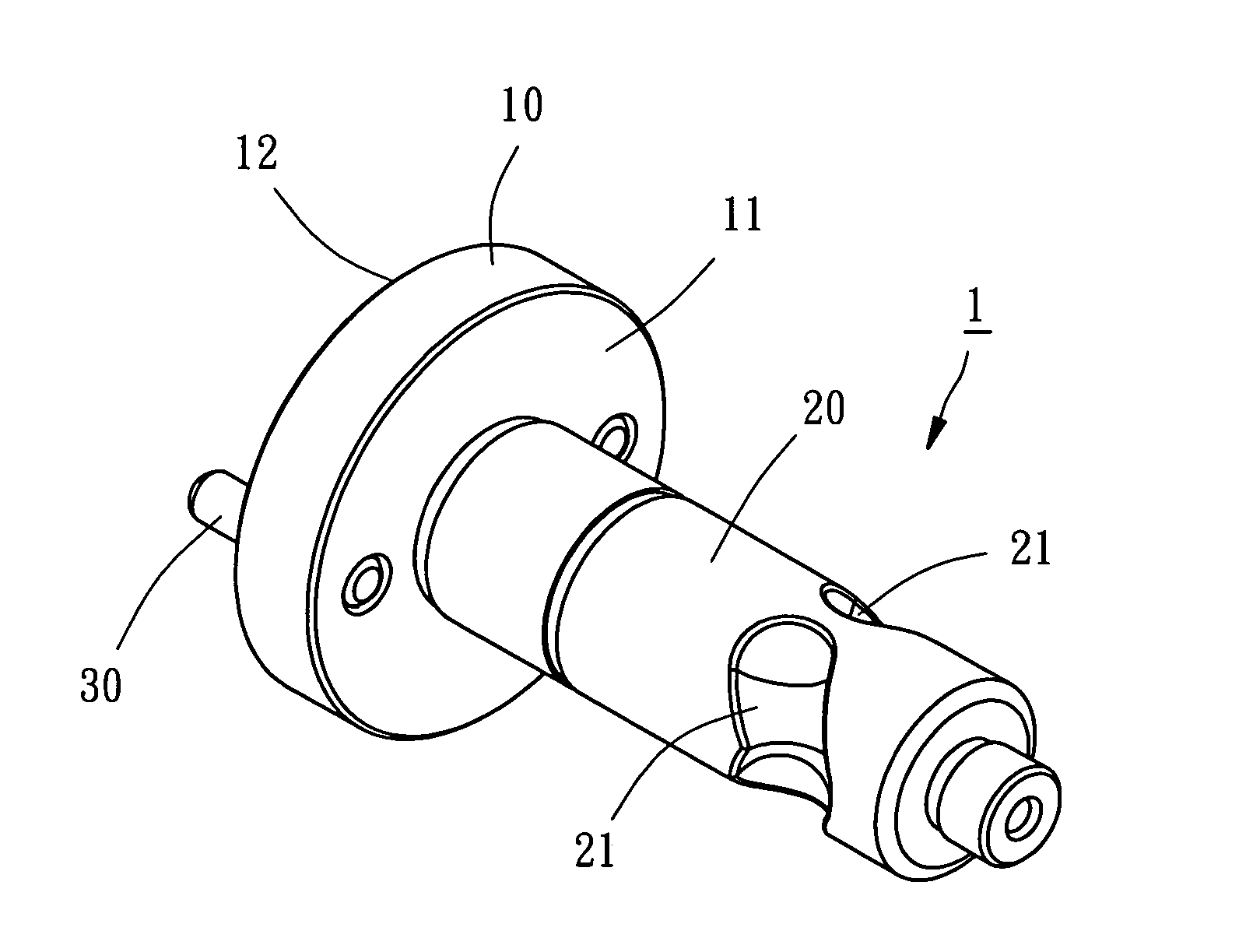
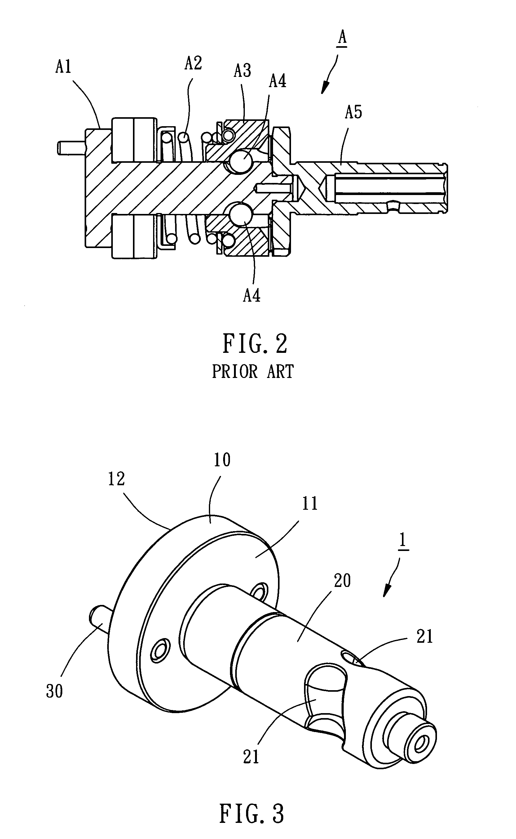
[0019]As shown in FIGS. 3-6, a shaft 1 for use in a power impact tool, such as an electrical impact screwdriver, an electrical impact wrench, and etc., in accordance with a first preferred embodiment of the present invention comprises a shaft base 10, a shaft body 20 and two gear carriers 30.

[0020]The shaft base 10 has a short cylinder-like shape, having a first end face 11 and a second end face 12 opposite to the first end face 11.

[0021]The shaft body 20 is shaped like a round rod and coaxially connected with its one end to the first end face 11 of the shaft base 10. The shaft body 20 has two actuating slots 21 of same shape symmetrically equiangularly formed on the periphery at two sides of the shaft body 20. Each actuating slot 21 has two distal ends disposed relatively closer to the shaft base 10 than the middle part of the actuating slot 21.

[0022]The two gear carriers 30, which are respectively embodied as a rod member in this embodiment, symmetrically and perpendicularly exten...


PUM


Abstract

A shaft for a power impact tool includes a shaft base and a shaft body perpendicularly extending from the center of a first end face of the shaft base. The shaft body has two actuating slots symmetrically formed on the periphery thereof at two sides and provided with a middle part and two distal ends disposed relatively closer to the shaft base than the middle part. The shaft base has a second end face on which at least two recesses are symmetrically formed, and a hole coaxially extending from the center of the second end face toward the inside of the shaft body with a predetermined distance in such a manner that the center axis of the hole is same as the center axis of the shaft body to effectively diminish possible vibration during rotation of the shaft.

Description

BACKGROUND OF THE INVENTION[0001]1. Field of the Invention[0002]The present invention relates to power impact tools, such as pneumatic impact wrenches and electrical impact screwdrivers, and more specifically, to a shaft for the power impact tool.[0003]2. Description of the Related Art[0004]A power impact tool that outputs a rotary driving force, such as a pneumatic impact wrench, an electrical impact screwdriver, and etc., will output a continuous impact force rapidly corresponding to the direction of rotation when the output rotary driving force encounters a resistance, thereby facilitating performance of rotating the workpiece.[0005]As shown in FIGS. 1 and 2, an impact generating mechanism A of a conventional electrical tool comprises a shaft A1, a spring A2, an impact member A3, two actuating steel balls A4, and an output member A5. The shaft A1 is used to rotate the impact member A3 which is in turn to rotate the output member A5. As soon as the output member A5 is stopped from...

Claims


Application Information

Patent Timeline
IPC IPC(8): B25D11/00
CPCB25B21/02B25B21/026
Inventor LU, CHIN-YI
Owner MOBILETRON ELECTRONICS
Why Eureka
Try Eureka