Sheet Conveying Device

a conveying device and sheet technology, applied in the direction of thin material processing, printing, article separation, etc., can solve the problems of not being removed, not attached to a portion of the belt, printing failure, etc., to prevent the effect of reducing the print quality due to the change of belt speed

Inactive Publication Date: 2008-03-27
BROTHER KOGYO KK
View PDF18 Cites 14 Cited by
  • Summary
  • Abstract
  • Description
  • Claims
  • Application Information

AI Technical Summary

Benefits of technology

[0015] Further, in one or more examples, a brush may be disposed near the inlet, either on the inside or the outside of the case, so as to contact a surface of the belt. Thus, foreign matters (e.g., debris, particles, unwanted material) attached to the surface of the belt may be removed effectively.
[0016] Additionally or alternatively, a guide configured to press the sheet onto the belt may be disposed at each end of an opening of the case. For example, when the sheet is pressed against and separated from the belt by a roller for pressing the sheet against the belt, changes in speed of the belt may be prevented. Thus, printing failure and reduction in print quality due to changes in speeds of the belt may also be prevented.

Problems solved by technology

However, foreign matters attached to a portion of the belt placed in a return run position will not be removed.
Therefore, as a portion of the belt in the return run position to which foreign matters become attached comes to the forward run position, the foreign matters may rise and adhere to nozzles of the print head, leading to printing failures.
As the diameters of the rollers increase, the belt may start to move slower, which ultimately reduces printing speeds.

Method used


Image

  • Sheet Conveying Device
  • Sheet Conveying Device
  • Sheet Conveying Device

Examples


Embodiment Construction

[0022] Embodiments are described in detail with reference to the accompanying drawings. One or more embodiments may be applied to inkjet printers that form characters and / or images by ejecting ink onto recording sheets.

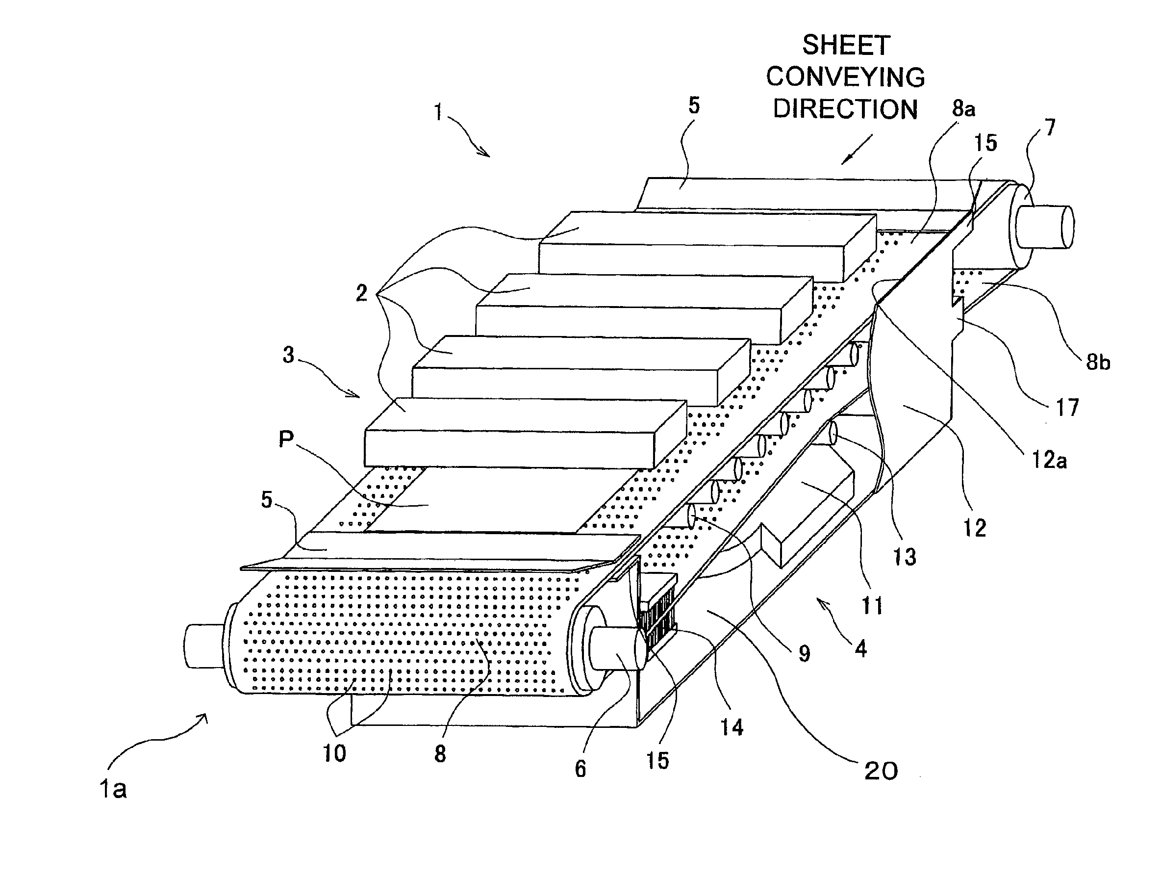
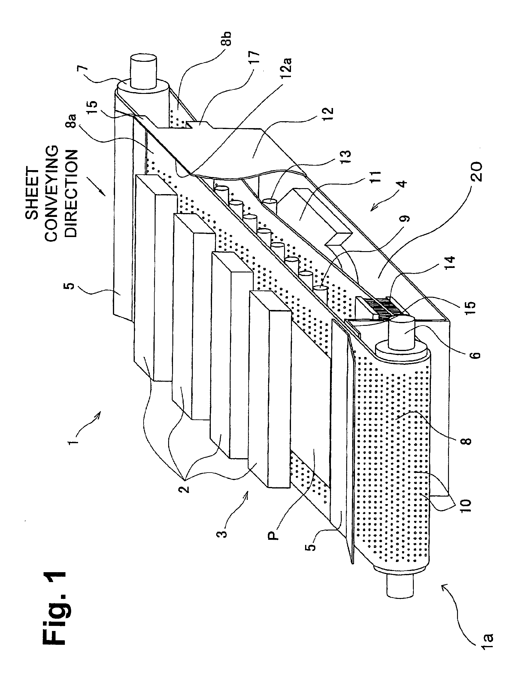
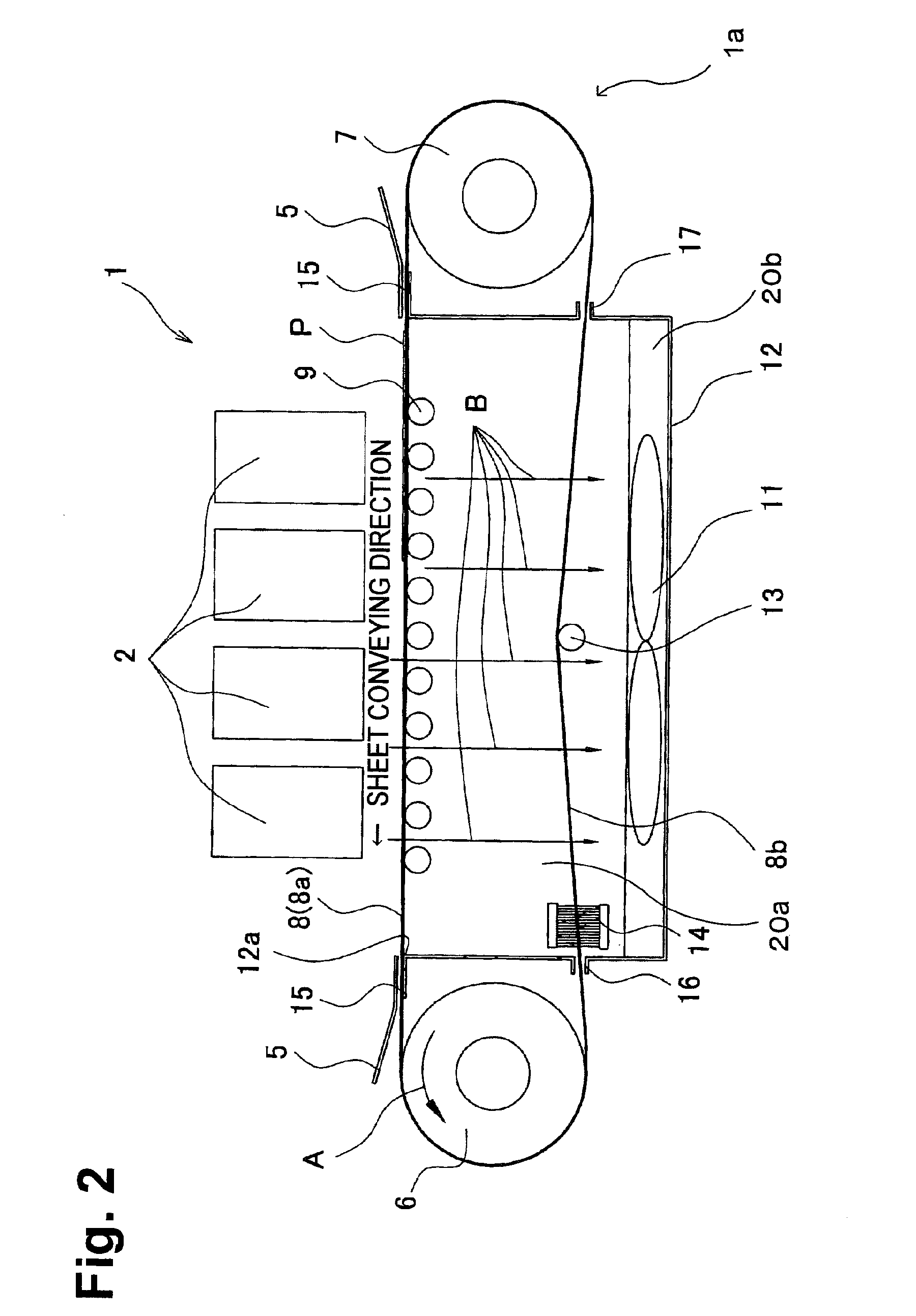
[0023] As shown in FIGS. 1 and 2, a color inkjet printer 1 comprises four print heads 2, and a sheet conveying device 1a including a conveyor unit 3 and a suction unit 4.

[0024] Inkjet printer 1 may be a line printer comprising four print heads 2, each of which corresponds to one of four ink colors (e.g., magenta, yellow, cyan and black) arranged in a sheet conveying direction. Each of the four print heads 2 may be of a hexahedral shape elongated in a direction perpendicular to the sheet conveying direction. Bottom surfaces of print heads 2 face a conveying belt 8. Ink droplets of each color are ejected to a print area defined on an upper print surface of a sheet P when sheet P, conveyed by the conveying belt 8 sequentially, passes under print heads 2. Thus, a color ...


PUM

PropertyMeasurementUnit
thicknessaaaaaaaaaa
pressureaaaaaaaaaa
tensionaaaaaaaaaa

Abstract

A sheet conveying device may include a belt having a plurality of throughholes, a fan disposed so as to interpose a portion of the belt placed in a return run position between the fan and a portion of the belt placed in the forward run position, and a case that defines a chamber with a portion of the belt placed in the forward run position. The fan creates a negative pressure within the chamber by drawing air through the throughholes of the endless belt, thereby removing dust and other unwanted particles and debris from the endless belt. In one or more examples, a brush may also be included to provide further removal of unwanted dust and particles. Further, in one or more configurations, the sheet conveying device may also include belt rollers and/or supporting members.

Description

CROSS REFERENCE TO RELATED APPLICATION [0001] The present application claims priority from Japanese Patent Application No. 2006-260067, which was filed on Sep. 26, 2006, the disclosure of which is herein incorporated by reference in its entirety. BACKGROUND [0002] 1. Technical Field [0003] Embodiments relate to a sheet conveying device configured to convey sheets. [0004] 2. Description of Related Art [0005] Current systems include sheet conveying devices comprising a belt mechanism configured to convey the recording medium and a platen disposed adjacent to an inner surface of a belt of the belt mechanism. In the sheet conveying device, a belt of the belt mechanism is moved by a pair of rollers in a running (i.e., a conveying) direction. The belt is formed of foamed material having breathability or air permeability. The platen has a suction opening and a suction fan to cause negative pressure in an interior of the platen. A recording medium is conveyed by the belt while being suction...

Claims


Application Information

Patent Timeline
Patent Type & Authority Applications(United States)
IPC IPC(8): B65H5/02B65H5/22
CPCB41J11/007B41J11/0085B65H2406/3124B65H11/005B65H2301/531B65H5/224
Inventor SAKAIDA, ATSUO
Owner BROTHER KOGYO KK
Why Eureka
Try Eureka