
Human powered vehicle drive system

a technology of drive system and human body, which is applied in the direction of rider propulsion, vehicle components, ambulance service, etc., can solve the problems of low speed comfortably achievable, poor ergonomics, and power stroke basic problems,

Inactive Publication Date: 2008-03-27
CHAIR FORCE ONE
View PDF52 Cites 33 Cited by
  • Summary
  • Abstract
  • Description
  • Claims
  • Application Information

AI Technical Summary

Benefits of technology

[0020]In a first aspect, the present invention provides a human powered vehicle drive system comprising a drive lever operatively connected to a drive rotor so that the drive rotor is constrained to rotate in a driving direction with respect to a vehicle frame when a power stroke is applied to the drive lever. The drive lever is pivotally mounted relative to the vehicle frame, and the drive rotor is rotatably mounted relative to the vehicle frame. A power-stroke assisting spring provides a power-stroke assisting torque to the drive lever about a drive-lever pivot to bias the drive lever in the power-stroke direction. The vehicle frame may be a wheelchair frame and the drive rotor a drive spool, where a tension element operatively connects the drive lever to the drive spool, unwinding from the drive spool and causing the drive spool to rotate in a driving direction when a power stroke is applied to the drive lever. In this arrangement, a spool rewind spring keeps the tension element taut and rewinds it onto the drive spool during a recovery stroke of the drive lever. Tension in the tension element due to the spool rewind spring causes a biasing torque on the drive lever in the recovery stroke direction, which may be greater than, equal to, or less than the power-stroke assisting torque provided by the power-stroke assisting spring.

Problems solved by technology

This arrangement is highly mechanically efficient; however the ergonomics are extremely poor.
The result is that only low speeds are comfortably attainable.
However, the basic ergonomic problems associated with the power stroke remain.
They are not as maneuverable or versatile as wheelchairs in general.
The drive levers may be pivoted at the wheel axle, but that configuration does not improve the forward and downward power stroke that is associated with chest cavity compression and forward upper spinal posture.
One disadvantage of these mechanisms is that there is friction between the driving elements.
Lubricants are also messy.
Another disadvantage of these mechanisms is that separate load paths involving duplication of mechanisms are required to enable a variety of drive ratios.
Therefore such a transmission with a larger number of available drive ratios will necessarily be more complicated, heavier, and more expensive than a similar mechanism with fewer available drive ratios.
This method employs trigonometric effects and does indeed vary the effective drive ratio.
This modulating pulley is in the load path and can only reduce mechanical efficiency.
This is obviously heavy and high maintenance.
This is awkward because, for example, the brake lever which is located at the drive lever handle cannot be actuated during a change of drive ratios.
This is not the best posture for the wrist during the power stroke.
There is also the problem of shifting the transmission into a neutral or disconnected state to enable the occupant to position the drive levers without propelling the chair.
Although the flexible tension element drive systems alleviate the friction associated with gears, sprockets and cams, the systems have another source of wasted energy.
An amount of energy equal to the length of the power stroke at the cable attachment multiplied by the cable tension due to the recoil spring is wasted each power stroke.
However, the brake mechanisms disclosed are integral with the chair and not the removable wheel.
This adds to the weight of the chair which is already the heaviest component among the two quickly removable driven wheels and chair.
Furthermore, in such arrangements, attaching a wheel typically requires awkward maneuvering to align the brake stator and rotor, and subsequent adjustment or calibration of the brake system.
If a user forgets to adjust the brake system after reattaching a wheel, a dangerous operating condition may result.

Method used


Image

  • Human powered vehicle drive system
  • Human powered vehicle drive system
  • Human powered vehicle drive system

Examples


Embodiment Construction

[0049]While the present invention may be used in any vehicle or craft, particularly wherein a reciprocating input motion is converted to a rotating output motion, the example of a wheelchair is used to explain the invention in the following description and illustrated embodiments. In the interest of a clear description, the structure of a wheelchair is first outlined, and then the mechanisms of the lever drive system and associated features are described in detail.

Structural Elements of Wheelchair

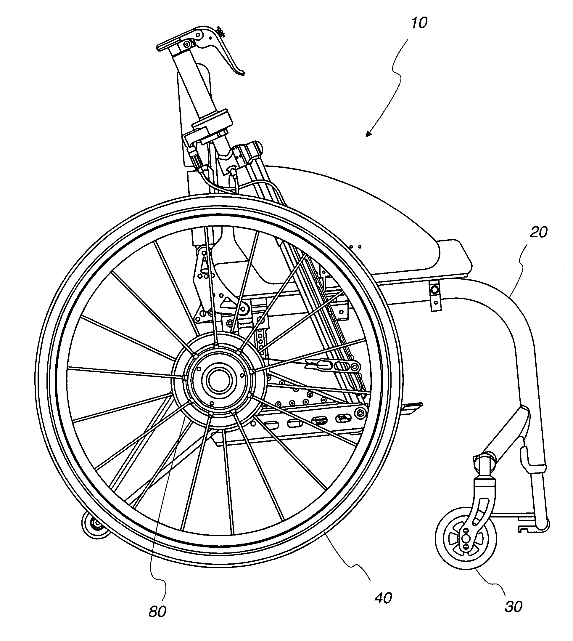
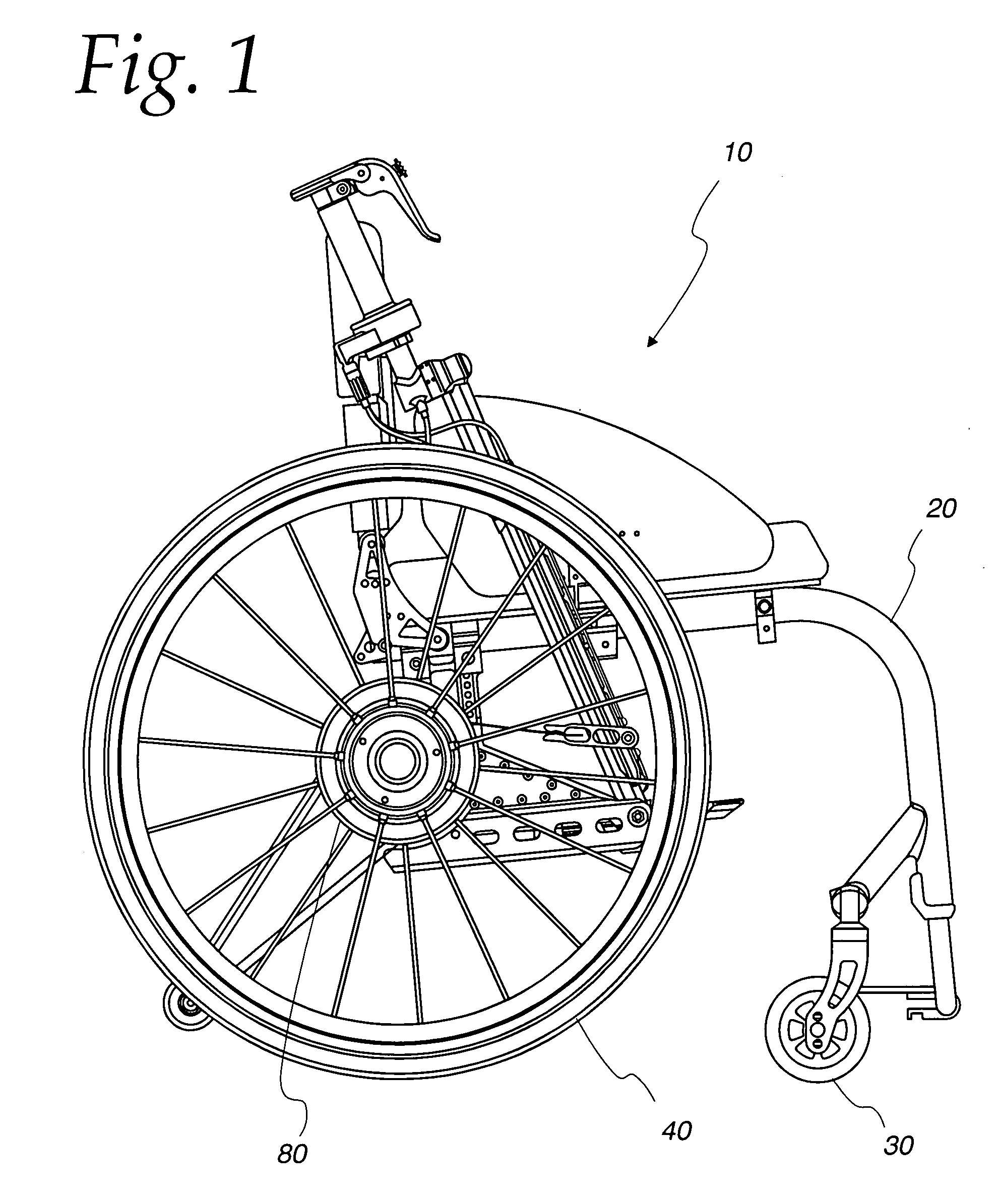
[0050]A lever drive wheelchair is generally designated as 10 in FIG. 1. Wheelchair 10 includes a conventional chair frame 20 with all the usual features known in the art. The front of chair 10 is supported on self steering casters 30. There are right and left casters for balance.

[0051]The rest of the weight of the chair is supported by the driven wheels 40. These can be provided with conventional hand rims (not shown) for conventional hand power and maneuvering. Again there is a right and a...


PUM


Abstract

The present invention provides a human powered vehicle drive system that includes a vehicle frame, a power system including a pivotable drive lever and a one-way clutch, a neutral shifting system, and a braking system. The drive lever may be coupled to a tension member that is associated with the drive lever and a drive spool, so that power is transmitted from the drive lever to the drive spool via the tension member, and from the drive spool to a driven wheel via the one-way clutch. A drive-ratio shifting control allows a user to vary a drive ratio by translating the attachment point of the tension member to the drive lever up or down the drive lever. A neutral shifting control allows the user to engage and disengage the one-way clutch. The braking system includes a flexible brake linkage routed along the drive lever. The drive-ratio shifting, neutral shifting, and braking controls may all be situated proximate to a drive lever handle adjustably coupled to the drive lever. Additionally, the drive lever is biased in the forward direction by power-stroke assisting springs, which store energy applied in recovery strokes applied to the drive levers, then releasing the energy to assist in forward power strokes. An assembly including the power system, neutral shifting system and brake system integrated with each driven wheel may be released from the chair by a quick release mechanism.

Description

CROSS-REFERENCE TO RELATED APPLICATIONS[0001]This application claims the benefit of U.S. Provisional Applications Nos. 60 / 847,128, filed Sep. 26, 2006, and 60 / 903,329, filed Feb. 26, 2007, the disclosures of which are hereby incorporated in their entireties.FIELD OF THE INVENTION[0002]The present invention relates generally to the field of human powered vehicles, and more specifically to human-powered wheelchairs. Still more specifically, the present invention relates to a human-powered wheelchair having a quickly releasable assembly including a drive-lever power system, a neutral shifting system, a brake system and a driven wheel.BACKGROUND OF THE INVENTIONWheelchair Drive Systems[0003]There have long been wheelchairs for mobilizing the injured or disabled under the power of the chair occupant, i.e., human powered wheelchairs. Human powered wheelchairs fall into three major groups. The first group is human powered wheelchairs that are propelled using hand rims which are nearly the ...

Claims


Application Information

Patent Timeline
Patent Type & Authority Applications(United States)
IPC IPC(8): B62M3/00B62M1/14
CPCA61G5/023A61G5/025A61G2005/1089A61G5/1035A61G5/101A61G5/1027A61G5/1008A61G5/1089
Inventor PATTERSON, SAM HARWELL
Owner CHAIR FORCE ONE
Learn More