Multi-Frequency Metal Detector Having Constant Reactive Transmit Voltage Applied To A Transmit Coil

Active Publication Date: 2008-03-27
MINELAB ELECTRONICS
View PDF6 Cites 21 Cited by
  • Summary
  • Abstract
  • Description
  • Claims
  • Application Information

AI Technical Summary

Benefits of technology

[0042]In preference the transmit electronics is adapted to effect an effective negative resistance which is selected to be approximately equal in magnitude but opposite to the resistance of the effective resistive component impedance met by the transmit voltage signal, the negative effective resistance being in series with the transmit coil.
[0043]

Problems solved by technology

One problem with metal detectors which transmit more than one frequency and are used to search an environment of varying magnetic permeability such as magnetic soils, is that the transmit coil's effective inductive component imp

Method used


Image

  • Multi-Frequency Metal Detector Having Constant Reactive Transmit Voltage Applied To A Transmit Coil
  • Multi-Frequency Metal Detector Having Constant Reactive Transmit Voltage Applied To A Transmit Coil
  • Multi-Frequency Metal Detector Having Constant Reactive Transmit Voltage Applied To A Transmit Coil

Examples


Embodiment Construction

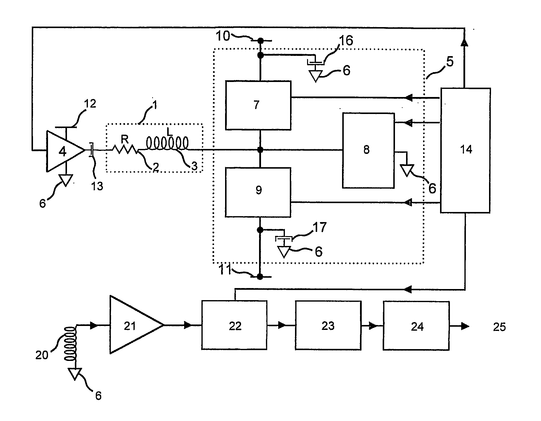
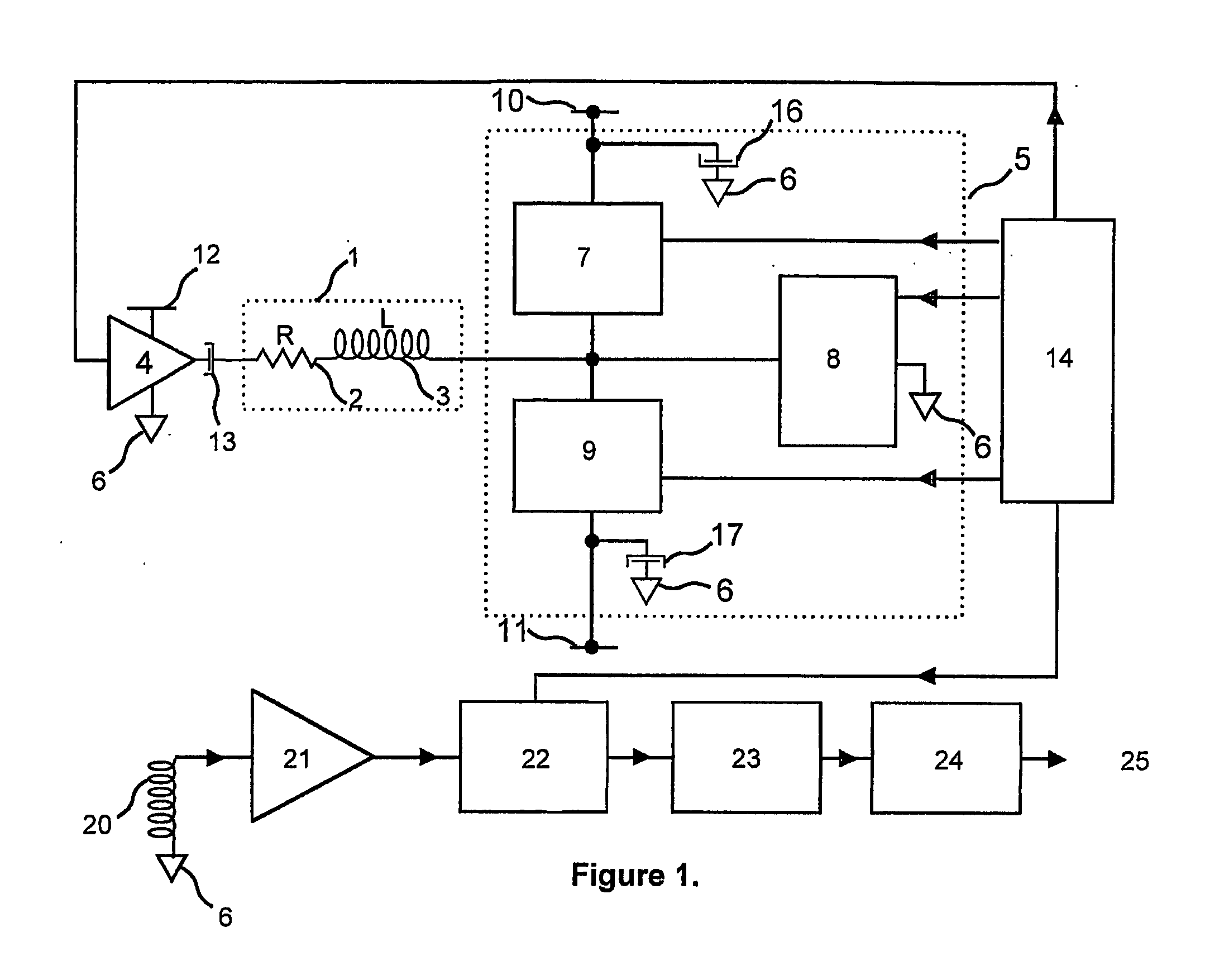
[0052]Referring specifically to the drawing transmit coil 1 approximately may be represented by an effective resistance component impedance 2 of value R in series with an effective inductive component impedance 3 of inductance value L. This is connected to transmit electronics which may generate a transmit signal applied to the transmit coil. This transmit electronics may include a series capacitor 13 connected to an active generator 4 which includes at least a linear amplifier. The transmit electronics also includes switching voltage electronics 5 which in this example consists of three low impedance solid state switches 7, 8 and 9, which is also connected to the transmit coil. Switch 7 is connected to a power supply supplying supply input 10, switch 9 to a power supply supplying supply input 11 and switch 8 to earth 6. Power supply input 10 is a.c. coupled to earth via storage capacitor 16 and power supply input 11 is a.c. coupled to earth via storage capacitor 17. The switches 7,...


PUM


Abstract

An electronic metal detector having a transmit coil (1) adapted to transmit an alternating magnetic field associated with a reactive transmit voltage, wherein the transmit voltage signal is selected such that the reactive transmit voltage is approximately constant for at least a time period during which a magnetic field signal to be processed is received by the detector for processing.

Description

TECHNICAL FIELD[0001]This invention relates to metal detectors and methods of metal detection.[0002]The invention relates in particular to a method of assisting accuracy of generation of a constant reactive voltage and of implementing low power electronic circuitry whilst maintaining constant reactive transmit voltages.[0003]This invention has particular application to metal detectors which are to operate in environments of varying magnetic permeability, such as magnetic soils, which may alter the inductance of a transmit coil during interrogation of such an environment.BACKGROUND ART[0004]A reactive transmit voltage may have a waveform such as a rectangular waveform or a pulsed signal sequence, depending on a required application.[0005]The concepts described herein are also useful for the detection of conductors whether these are ferrous materials or non-ferrous materials but which are relatively good electrical conductors in environments containing relatively mildly conducting mat...

Claims


Application Information

Patent Timeline
IPC IPC(8): G01V3/11G01V3/10
CPCG01V3/104
Inventor CANDY, BRUCE HALCRO
Owner MINELAB ELECTRONICS
Why Eureka
Try Eureka