
Miniaturized planar antenna of digital television

a digital television and planar antenna technology, applied in the direction of elongated active element feed, resonant antenna, radiating element structure, etc., can solve the problems of unavoidable tendency to miniaturize a broadband antenna of digital television, rather poor electromagnetic signal transmission efficiency, etc., to improve the signal transmission efficiency of a miniaturized antenna

Active Publication Date: 2008-03-27
WISTRON NEWEB
View PDF0 Cites 13 Cited by
  • Summary
  • Abstract
  • Description
  • Claims
  • Application Information

AI Technical Summary

Benefits of technology

[0009] For improving the signal transmission efficiency of a miniaturized antenna combined to a portable electronic device such as a cellular telephone, notebook computer or PDA and used for receiving digital television signals, the present invention is proposed.
[0010] The main object of the present invention is to provide a miniaturized planar antenna of digital television, capable of elevating the electromagnetic signal transmission efficiency.
[0011] Another object of the present invention is to provide a miniaturized planar antenna of digital television, capable of broadening a bandwidth of the electromagnetic signal transmission of an electronic device.
[0012] For attaining to the objects of the present invention mentioned above, a miniaturized planar antenna of digital television comprises an insulation plate, a metal radiator used for allowing the antenna to receive electromagnetic signals, combined to a first surface of the insulation board and including a meander line, a metal grounding element used for a grounding terminal of the antenna and combined to a second surface of the insulation plate and a metal parasitic element, combined to a second surface of the insulation plate, corresponding to a position of the metal radiator and including a meander line provided with a first end thereof electrically connected to the metal grounding element. whereby, a bandwidth that the antenna receives electromagnetic signals can be broadened by means of the metal parasitic element so as to elevate the transmission efficiency of the electromagnetic signals.

Problems solved by technology

Accompanying the development of the combination of a digital television and a portable electronic product such as a cellular telephone, notebook computer or PDA, miniaturizing a broadband antenna of the digital television is an unavoidable tendency.
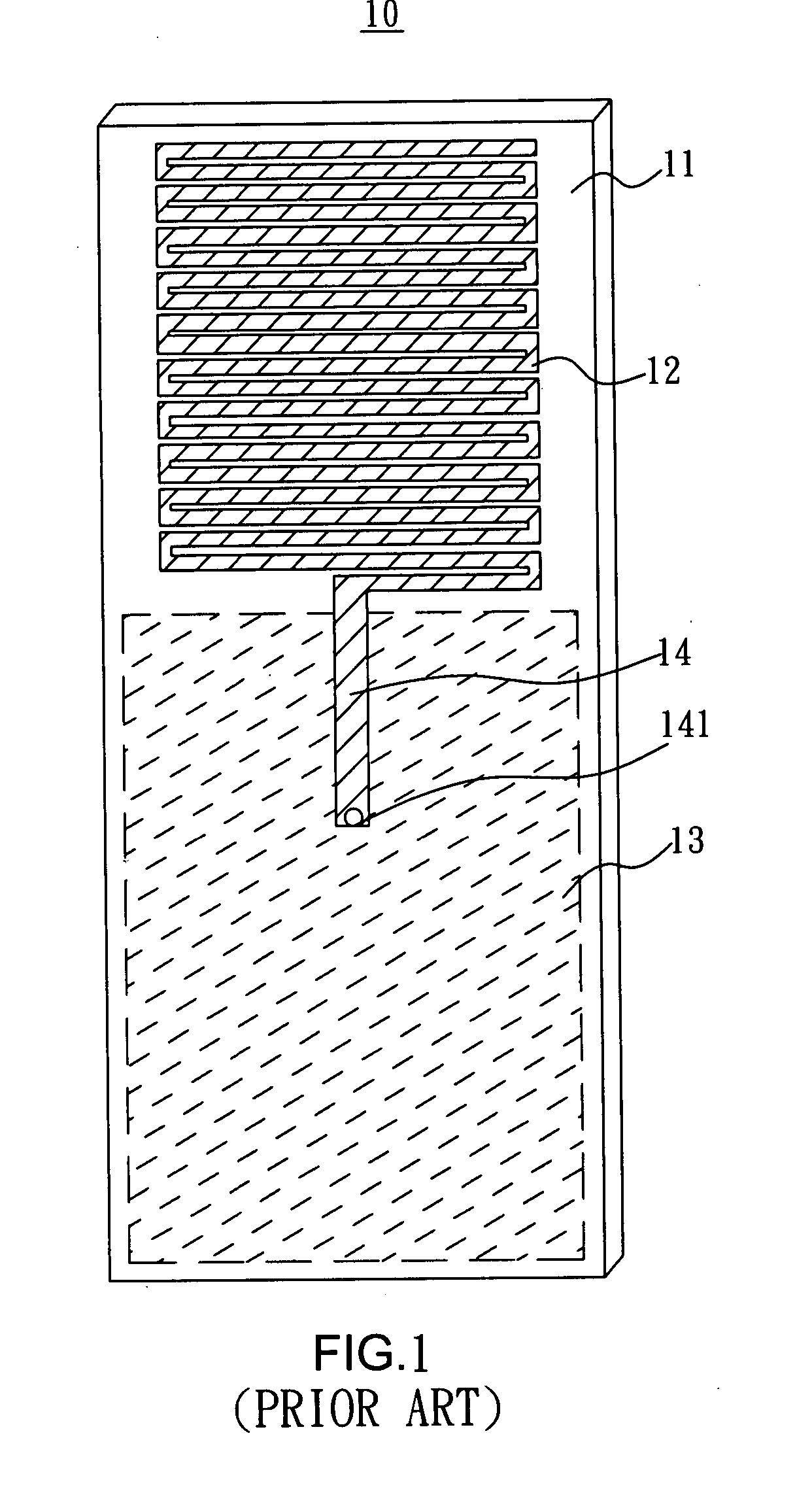
The antenna 10 mentioned above can attain to the requirement of the miniaturization, but the bandwidth thereof is rather narrow such that the electromagnetic signal transmission efficiency is rather bad.

Method used


Image

  • Miniaturized planar antenna of digital television
  • Miniaturized planar antenna of digital television
  • Miniaturized planar antenna of digital television

Examples


Embodiment Construction

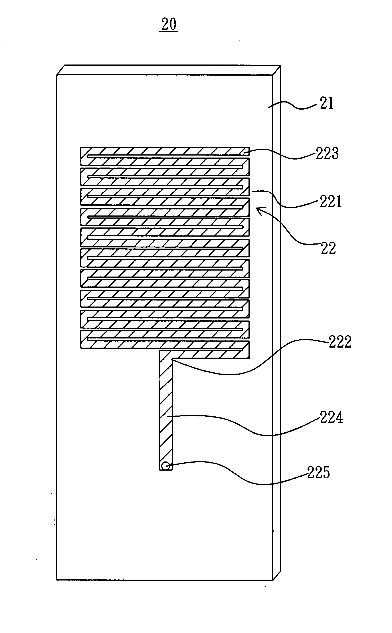
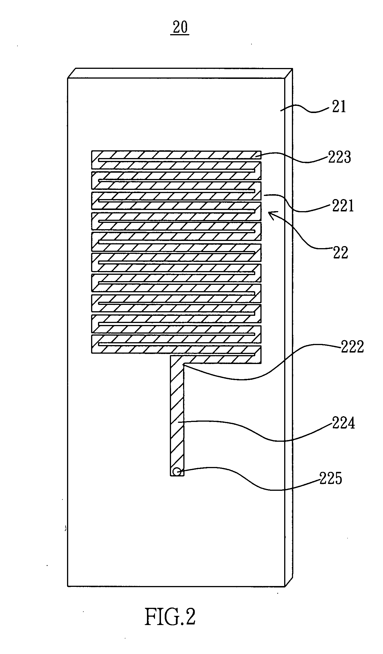
[0022] Please refer to FIGS. 2, 3A and 3B. A miniaturized planar antenna of digital television according to the present invention is used for being combined with a portable electronic device such as a cellular telephone, notebook computer and PDA so as to increase the efficiency of digital television signal transmission by means of the antenna. An antenna 20 of a first embodiment according to the present invention comprises an insulation plate 21, a metal radiator 22, a metal grounding element 23 and a metal parasitic element 24. The insulation plate 21 can be made from a general circuit board material.

[0023] The metal radiator 22 is used for allowing the antenna 20 to receive electromagnetic signals; the metal radiator 22 is combined with a first surface of the insulation plate 21; the radiator 22 includes a meander line portion 221, the meander line portion 221 has a first end 222 and second end 223; the first end 222 is connected to a micro-strip line 224, one end of the micro-s...


PUM


Abstract

A miniaturized planar antenna of digital television comprises an insulation plate a metal radiator combined with a first surface thereof, a metal grounding element connected to a second surface thereof and a metal parasitic element. The metal radiator has a meander line portion and the metal parasitic element also has a meander line portion and is corresponding to a position of the metal radiator; the transmission efficiency of digital television signals can be elevated by broadening an electromagnetic signal receiving bandwidth of the antenna by means of the metal parasitic element.

Description

BACKGROUND OF THE INVENTION [0001] 1. Field of the Invention [0002] The present invention relates to an antenna of a portable electronic device such as cellular phone, notebook computer or personal digital assistant, and more particularly to an antenna used for receiving digital television signals. [0003] 2. Description of Related Art [0004] There are many antennas used for receiving digital television signals such as the ones disclosed in U.S. Pat. No. 6,819,297, U.S. Pat. No. 6,639,555, U.S. Pat. No. 6,259,416, Taiwan Patent No. I255,589, I240,451 and M285,154, and Taiwan Patent Publication No. 521,455. [0005] Among these, Taiwan Patent Publication No. 521,455 discloses a miniaturized planar antenna of digital television, it comprises a base plate whose upper and lower surfaces respectively are a strip line formed by copper foil printing and a plurality of parallel rampart-line-typed antennas formed by copper foil printing and respectively disposed on the upper and the lower surfa...

Claims


Application Information

Patent Timeline
Patent Type & Authority Applications(United States)
IPC IPC(8): H01Q1/38
CPCH01Q1/38H01Q19/005H01Q9/42H01Q9/40
Inventor HUANG, JIUNN-MINGCHEN, CHIH-LUNGTSENG, KUAN-HSUEH
Owner WISTRON NEWEB
Learn More