Clock extraction method for patterned medium, clock extraction circuit for patterned medium and patterned medium

a clock extraction and clock technology, applied in the field of clock extraction method for patterned medium, clock extraction circuit for patterned medium and patterned medium, can solve the problem that the method of matching the position of the clock signal with the position of the magnetic dot has not been achieved for the magnetic disk apparatus using patterned medium

Inactive Publication Date: 2008-03-27
TOSHIBA STORAGE DEVICE CORP
View PDF9 Cites 4 Cited by
  • Summary
  • Abstract
  • Description
  • Claims
  • Application Information

AI Technical Summary

Benefits of technology

[0030]This configuration makes it possible to detect the reference dot of the nonmagnetic part and synchronize the clock signal with a timing of the reference dot being detected. In this event, a setup of a distance from the reference dot to the magnetic dot of the magnetic part at integer times of a center distance between adjacent dots, for example, makes it possible to match a timing of the clock signal with the magnetic dot of the magnetic part.

Problems solved by technology

Conventionally, however, a method for matching a clock signal with the position of the magnetic dot has not been accomplished for a magnetic disk apparatus using a patterned medium.

Method used


Image

  • Clock extraction method for patterned medium, clock extraction circuit for patterned medium and patterned medium
  • Clock extraction method for patterned medium, clock extraction circuit for patterned medium and patterned medium
  • Clock extraction method for patterned medium, clock extraction circuit for patterned medium and patterned medium

Examples


first embodiment

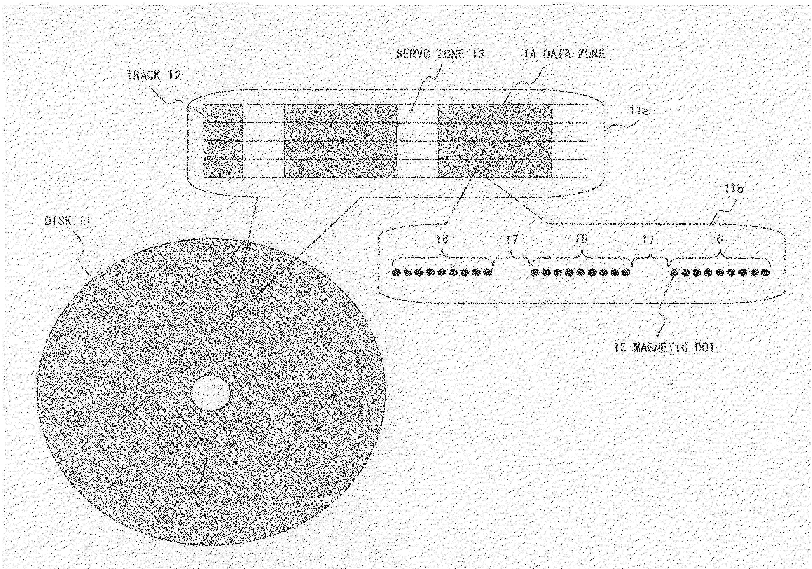
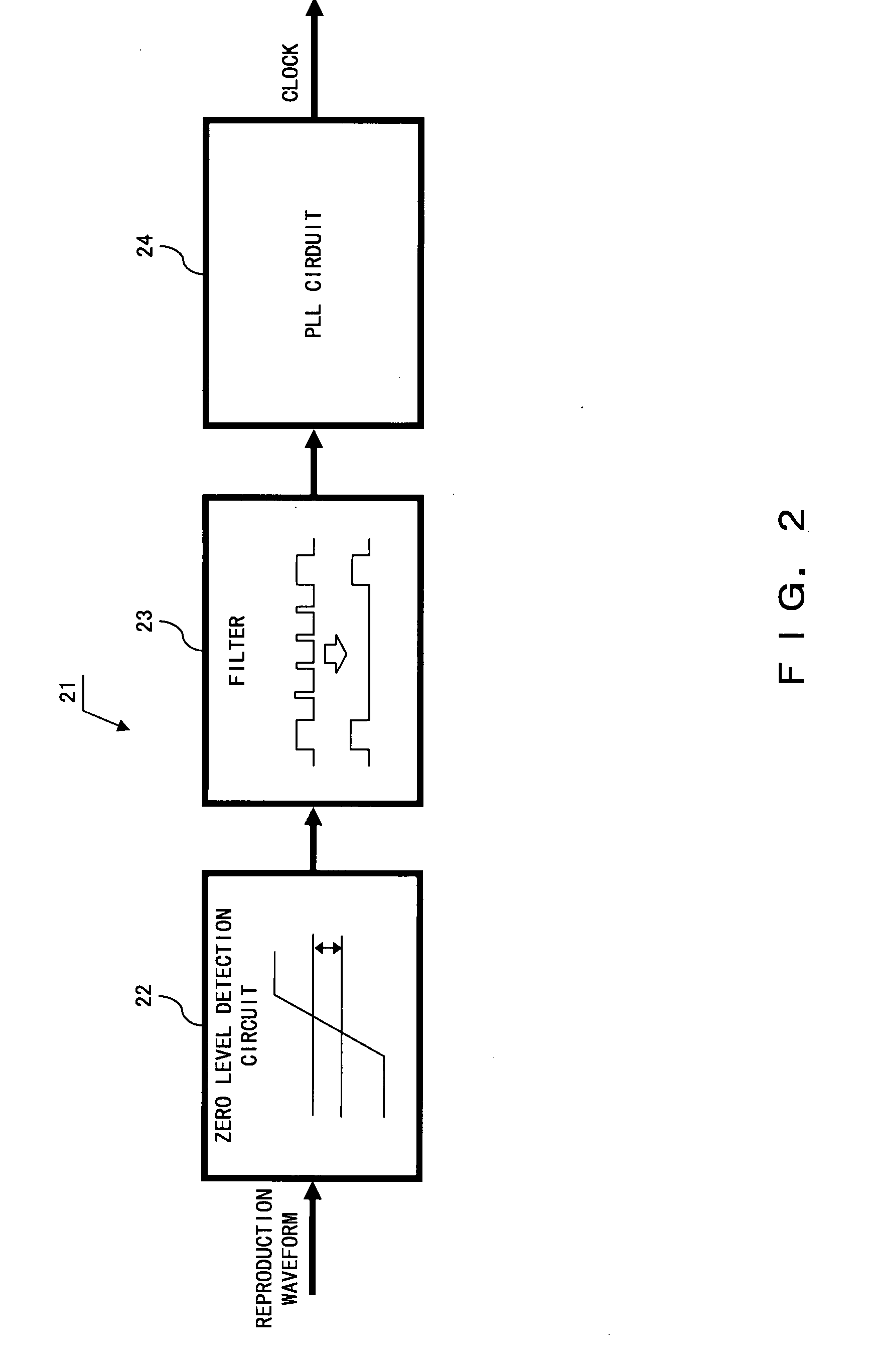
[0043]The following is a description of the preferred embodiments of the present invention by referring to the accompanying drawings. FIG. 1 is a diagram showing a structure of a patterned medium 11 according to a

[0044]FIG. 1 shows the patterned medium 11 and its partial enlargement diagrams 11a and 11b. The patterned medium 11 is featured with a plurality of tracks 12 in a concentric circular pattern with each track 12 being arrayed, at constant intervals, with servo zones 13 recording data used for controlling positions of writing and reading the patterned medium 11, and data zones 14.

[0045]Magnetic parts 16 arraying magnetic dots 15 at certain intervals for recording a magnetic signal and nonmagnetic parts 17 in which a magnetic dot 15 does not exist (i.e., a magnetic signal is not recorded therein) are featured in the data zone 14. A production method for the patterned medium 11 can use a conventional production method.

[0046]Featured in the patterned medium 11 are the magnetic p...

second embodiment

[0072]Next, FIG. 7 is a block diagram of a clock extraction circuit 61 according to a The same component signs are assigned to the same blocks as one shown in FIG. 2, and description on them are omitted in the following description.

[0073]The clock extraction circuit 61 comprises a zero level detection circuit 22 for detecting a zero level of a reproduction waveform, a filter 23, a differential circuit 62 for differentiating a reproduction waveform, a zero-cross detection circuit 63 for detecting a zero cross of a differential signal and a PLL circuit 24. The differential circuit 62 and zero-cross detection circuit 63 correspond to a slope detection circuit for detecting a slope of a reproduction waveform.

[0074]FIG. 8 is a circuit diagram of the differential circuit 62. The differential circuit 62 is constituted by a capacitor C2 to which a reproduction waveform is input, a resistor R2 of which one end is connected to the other end of the capacitor C2 and the other end is grounded, ...

third embodiment

[0093]Next, FIG. 11 is a diagram showing a structure of a patterned medium (i.e., a disk) 81 according to a

[0094]The patterned medium 81 according to the third embodiment is featured with a reference dot 82 at the center of a nonmagnetic part 17, as shown in FIG. 11.

[0095]A data zone 14 of the patterned medium 81 is featured with a magnetic part 16 arraying magnetic dots 15 at certain intervals as in the case of the patterned medium 11 of FIG. 1, and a nonmagnetic part 17 having a reference dot 82 at the center and not arraying a magnetic dot 15 in other parts. The difference between the patterned medium 81 shown in FIG. 11 and the patterned medium 11 shown in FIG. 1 is whether or not the reference dot 82 is featured at the center of the nonmagnetic part 17.

[0096]A clock extraction circuit of a magnetic disk apparatus according to the third embodiment comprises, likewise FIG. 7, a zero level detection circuit 22 for detecting a zero level of a reproduction waveform, a filter 23, a d...


PUM

PropertyMeasurementUnit
magnetism detectionaaaaaaaaaa
magneticaaaaaaaaaa
nonmagneticaaaaaaaaaa

Abstract

Aimed at is to match a timing of a clock signal with a magnetic dot of a patterned medium. A magnetic part arraying magnetic dots for recording a magnetic signal at certain intervals and a nonmagnetic part not recording a magnetic signal are featured in the patterned medium. A position of the nonmagnetic part not recording a magnetic signal is detected by a magnetic head and a clock signal is synchronized with a detection signal of the nonmagnetic part.

Description

BACKGROUND OF THE INVENTION[0001]1. Field of the Invention[0002]The present invention relates to a clock extraction method using a patterned medium, a clock extraction circuit therefor, a magnetic disk apparatus and a patterned medium.[0003]2. Description of the Related Art[0004]A patterned medium having a magnetic dot pattern corresponding to a data bit possesses a characteristic of increasing a recording density than a hard disk which is structured by a magnetic continuous film.[0005]A patterned medium needs to form magnetic dots at certain intervals, also requiring the surface of the magnetic dots to be flat so that the magnetic dots are flush with the surface of a substrate of the medium. This has conventionally necessitated a grinding process called a chemical mechanical grinding at the end of a production process of the media, thereby making the surface thereof flat.[0006]A patent document 1 notes a method for omitting the chemical mechanical grinding process in a production p...

Claims


Application Information

Patent Timeline
Patent Type & Authority Applications(United States)
IPC IPC(8): G11B5/09
CPCB82Y10/00G11B5/59616G11B5/743G11B5/746G11B20/14G11B2220/2516G11B5/855G11B5/02G11B5/65G11B5/85
Inventor IZUMI, HARUHIKO
Owner TOSHIBA STORAGE DEVICE CORP
Why Eureka
Try Eureka