
Lighting systems

a lighting system and light source technology, applied in the field of lighting systems, can solve the problems of high power consumption of photographic lighting systems, drawbacks of using different light sources in a single photographic light system,

Inactive Publication Date: 2008-03-27
HIGH LIGHTING
View PDF2 Cites 3 Cited by
  • Summary
  • Abstract
  • Description
  • Claims
  • Application Information

AI Technical Summary

Benefits of technology

[0009] LEDs are rated by the manufacturer at a specific current and voltage so as to assure the longevity of the LED. The controller may be configured to overdrive LEDs by increasing the voltage or current delivered to the LEDs beyond the manufacturer specifications or ratings so as to achieve greater illumination, which is necessary for many photographic applications. For example, if a Lamina Titan Turbo™ NT-54DO-487 light engine is used, overdriving the LEDs involves driving the LEDs beyond the manufacturer's recommendation of 10.8V@5A (which provides an output illumination of approximately 2000 lm).

Problems solved by technology

The use of different light sources in a single photographic light system presents drawbacks.
Another drawback to existing photographic lighting systems is their high power consumption.
Both the high intensity discharge lamps and the Xenon discharge tube exhibit poor efficiency characteristics with respect to power consumption.

Method used


Image

  • Lighting systems
  • Lighting systems
  • Lighting systems

Examples


Embodiment Construction

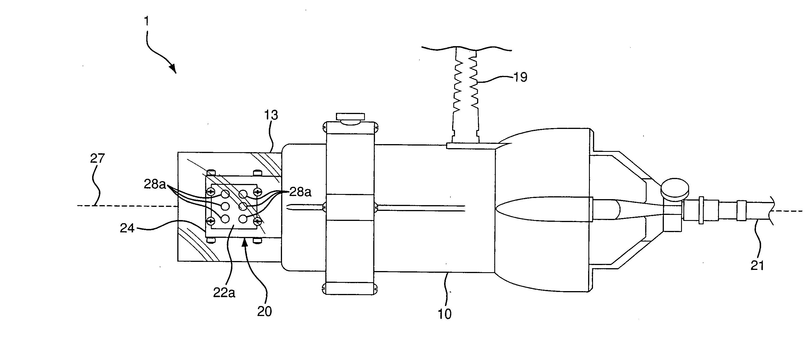
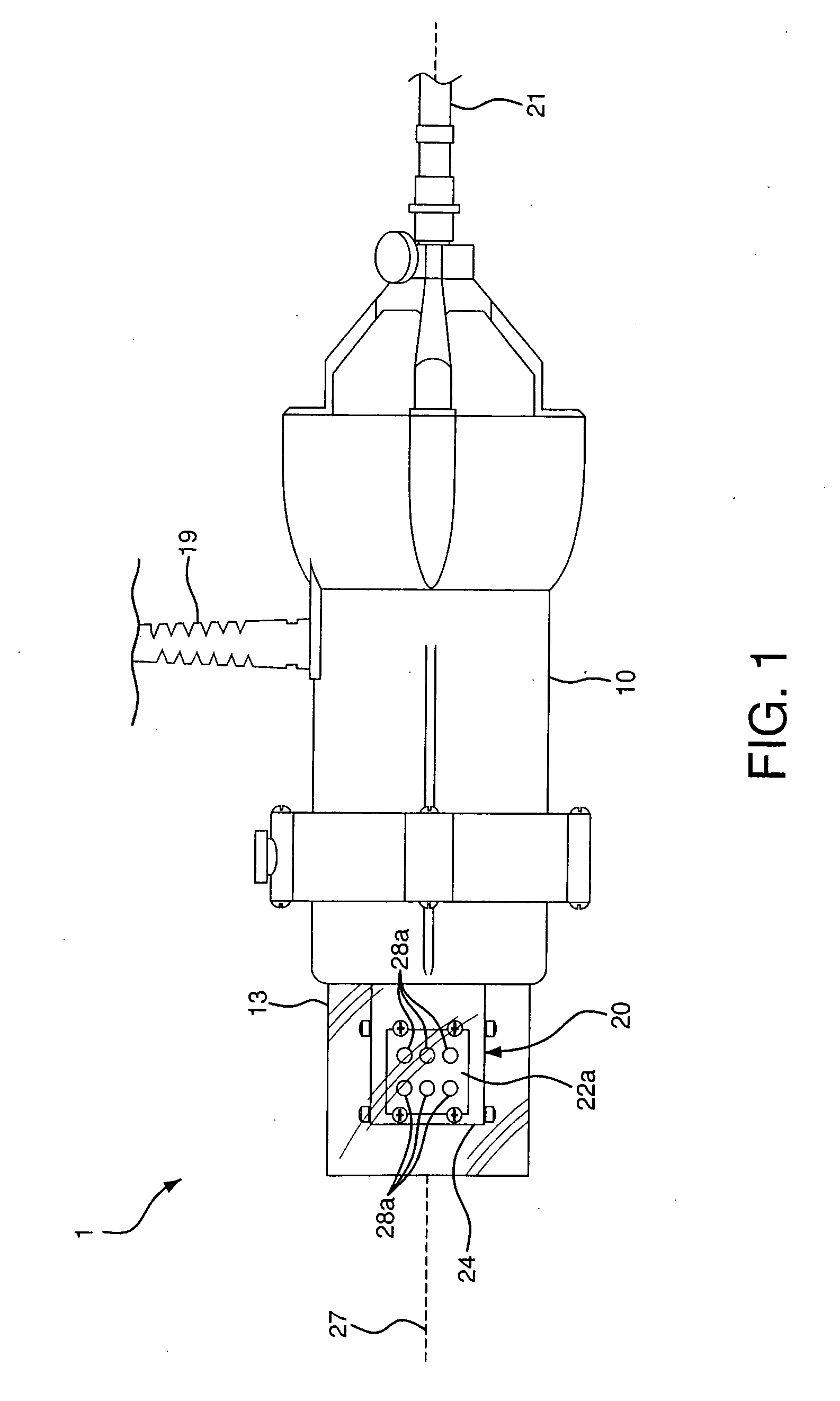
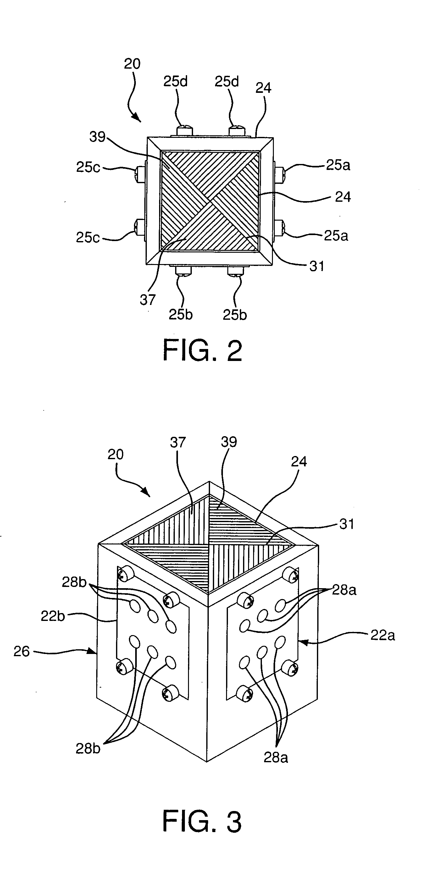
[0034] Referring to FIGS. 1 to 3, a lighting system 1 is shown including a housing 10 and a light source 20 mounted on the housing 10 including a body 24 (FIGS. 2 and 3) and four light engines 22a, 22b, 22c (hidden from view), and 22d (hidden from view) secured to the body 24. Each of the light engines 22a, 22b, 22c, and 22d includes one set of LEDs 28a, 28b, 28c (hidden from view), or 28d (hidden from view). The light source 20 may be electronically connected to a controller 40 (FIG. 11) for controlling the light source 20 via, e.g., a cable 21, as further detailed below. A cylindrical diffuser element 13 is disposed about the light source 20. The diffuser 13, which may be glass, is used to protect the light source 20 and to facilitate light distribution.

[0035] The housing 10 is generally cylindrical and includes spacing for receiving various components, for example, components for ventilation and to electrically connect the device to a power source and / or controller. Conventional...


PUM


Abstract

A lighting system, and method for using same, including a light source with one or more LEDs and a controller in communication with and adapted to control power flow to the light source. The LEDs may be overdriven by the controller in a flash setting so as to achieve a luminosity of approximately 1000% of their rated output for a short duration, and in another setting overdriven in a continuous mode so as to achieve a luminosity of approximately 250% their rated output.

Description

RELATED APPLICATIONS [0001] This application claims the benefit of U.S. Provisional Application No. 60 / 846,454, filed Sep. 22, 2006, the entire contents of which are hereby expressly incorporated herein by reference thereto.FIELD OF THE INVENTION [0002] The present application relates to lighting systems and methods for using the same. More particularly, the present application relates to LED lighting systems, and methods for their use, e.g., photography and film. BACKGROUND INFORMATION [0003] In the area of photography and film, current lighting systems typically use multiple light sources to illuminate a photographic subject. For example, an incandescent or high intensity discharge lamp (e.g., HMI lamp) may be used to deliver continuous illumination of the photographic subject for still photographs or filming. As it may be difficult to work under the intense light of the discharge lamp, the lamp may also be used at a lower intensity so as to provide preview lighting sufficient for...

Claims


Application Information

Patent Timeline
IPC IPC(8): F21V21/00F21V29/00F21V7/00H05B41/38
CPCG03B15/03
Inventor BRADSHAW, PETERSHARANEVYCH, OLEHCONNELL, JON
Owner HIGH LIGHTING
Learn More