
Use of minimal propagation delay path to optimize a mesh network

a mesh network and delay path technology, applied in the field of utility meters, can solve the problems of considerable industry problems, and the basic mechanical form of the register is typically limited in its output mode, and achieves the effect of avoiding the basic mechanical form of the register

Active Publication Date: 2008-03-27
ITRON GLOBAL SARL
View PDF9 Cites 22 Cited by
  • Summary
  • Abstract
  • Description
  • Claims
  • Application Information

AI Technical Summary

Benefits of technology

The present patent text describes an improved apparatus and methodology for an advanced metering system mesh network. The technical effects of this patent include improved cell isolation, reduced latency, and optimized network utilization. The methodology also includes a protocol for cell hopping in a frequency hopping network, and a method for selecting the shortest path for communication based on global propagation delay information. The patent also describes various improvements to the network such as embedding RF environmental evaluation tool features, computing average local propagation delay for each one-hop link, and utilizing statistical communication success rate to optimize network performance. Overall, the patent provides a solution for optimizing advanced metering systems in an open operational framework.

Problems solved by technology

The foregoing basic mechanical form of register was typically limited in its mode of output, so that only a very basic or lower level metrology function was achieved.
Implementing incremental changes in technology, such as retrofitting new features into existing equipment, or attempting to implement changes to basic components which make various components not interchangeable with other configurations already in the field, can generate considerable industry problems.

Method used


Image

  • Use of minimal propagation delay path to optimize a mesh network
  • Use of minimal propagation delay path to optimize a mesh network
  • Use of minimal propagation delay path to optimize a mesh network

Examples


Embodiment Construction

[0127] Various discussion herein makes us of and / or relies on abbreviations and acronyms, having the intended meanings as set forth in the appended Table of Definitions, which forms part of the present disclosure.

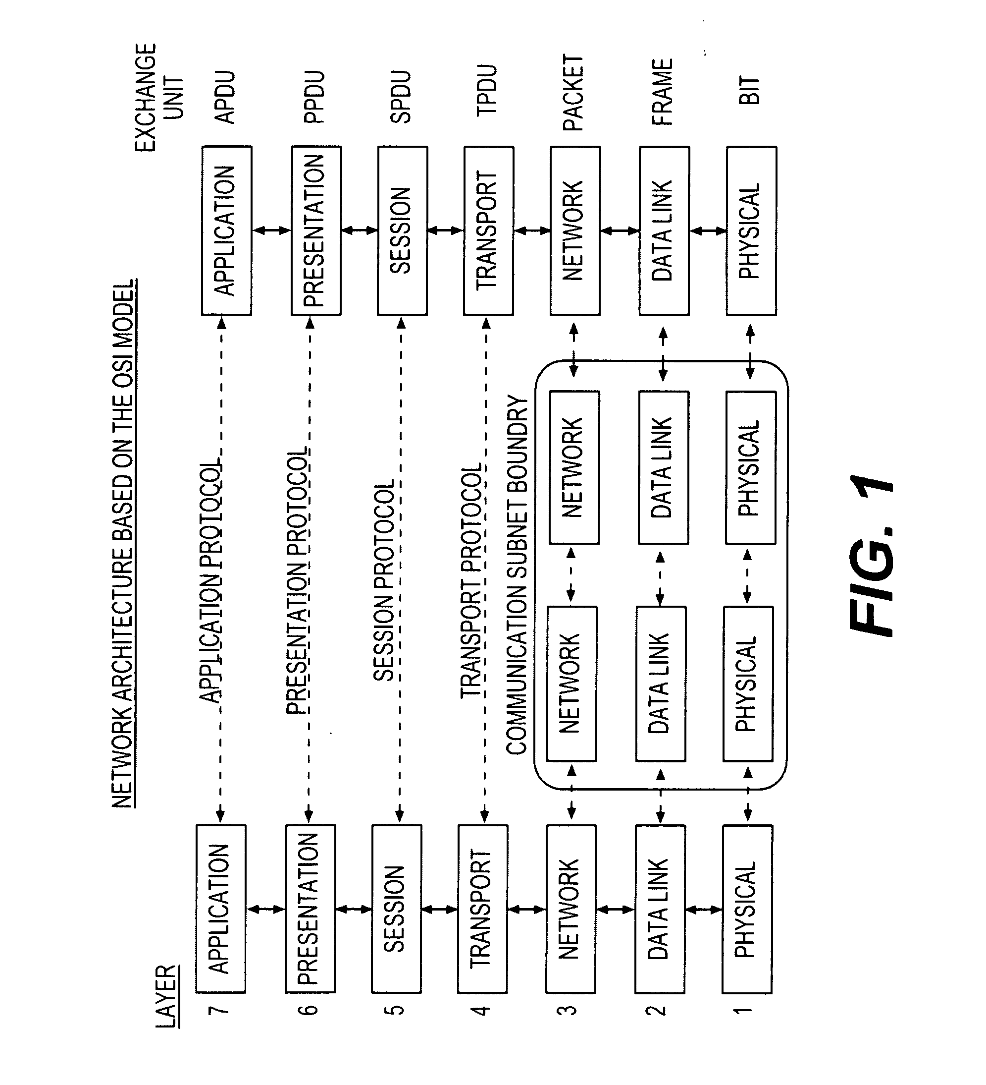
[0128] A reference model for interconnection of open systems (referred to as OSI-Open Systems Interconnection) has been described by ISO (the International Standards Organization). Such model, represented by present FIG. 1, is a functional decomposition of a communication system. In other words, the different layers perform different functions. A layer N offers services to the layer above N+1, by enhancing the services offered to this layer N by the underlying layer N−1. Such architecture allows further modifications on one layer without changing the others. Moreover, it allows compatibility between different protocols based on the same principle.

[0129] Selected combinations of aspects of the disclosed technology correspond to a plurality of different embodiments of the p...


PUM


Abstract

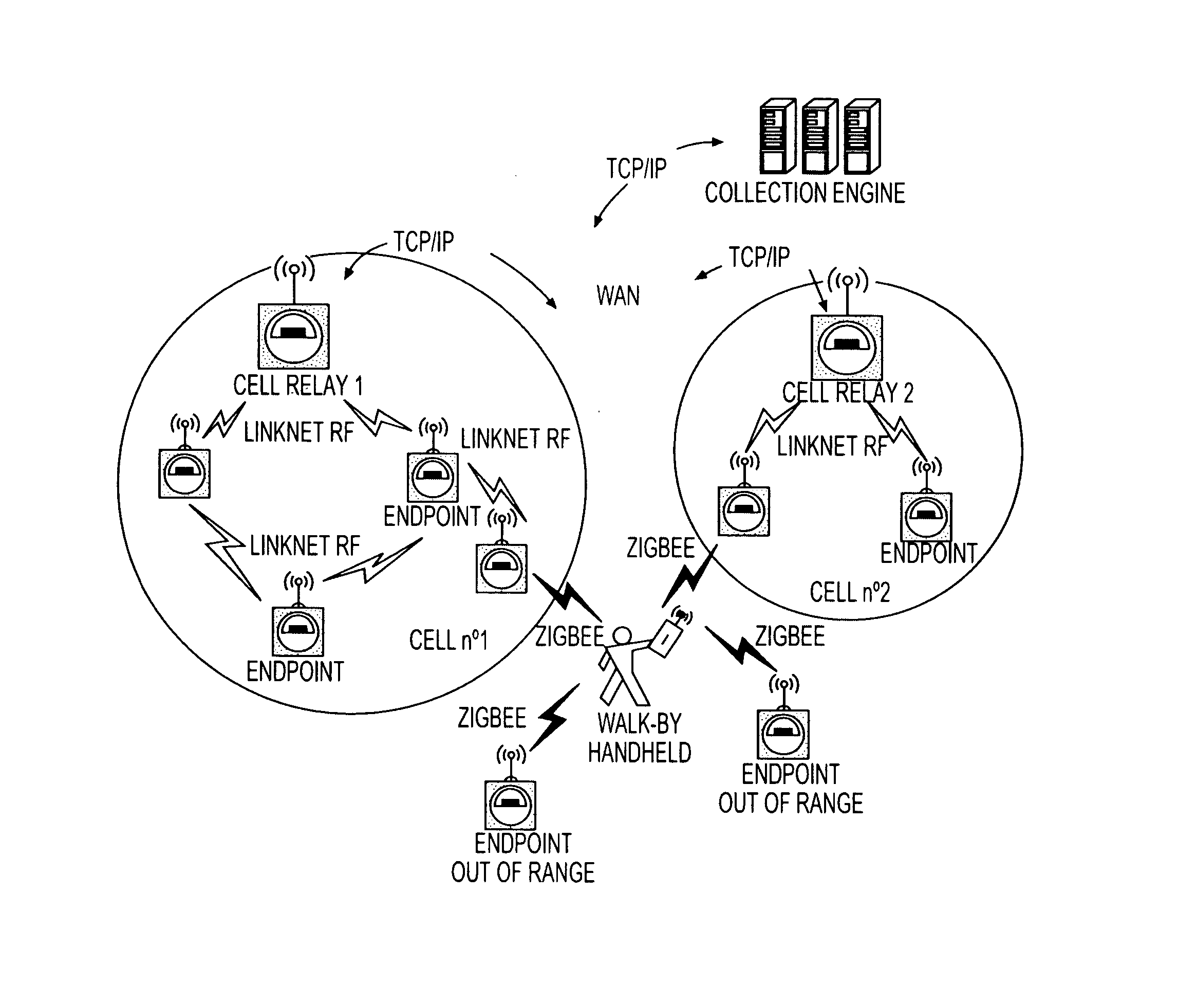
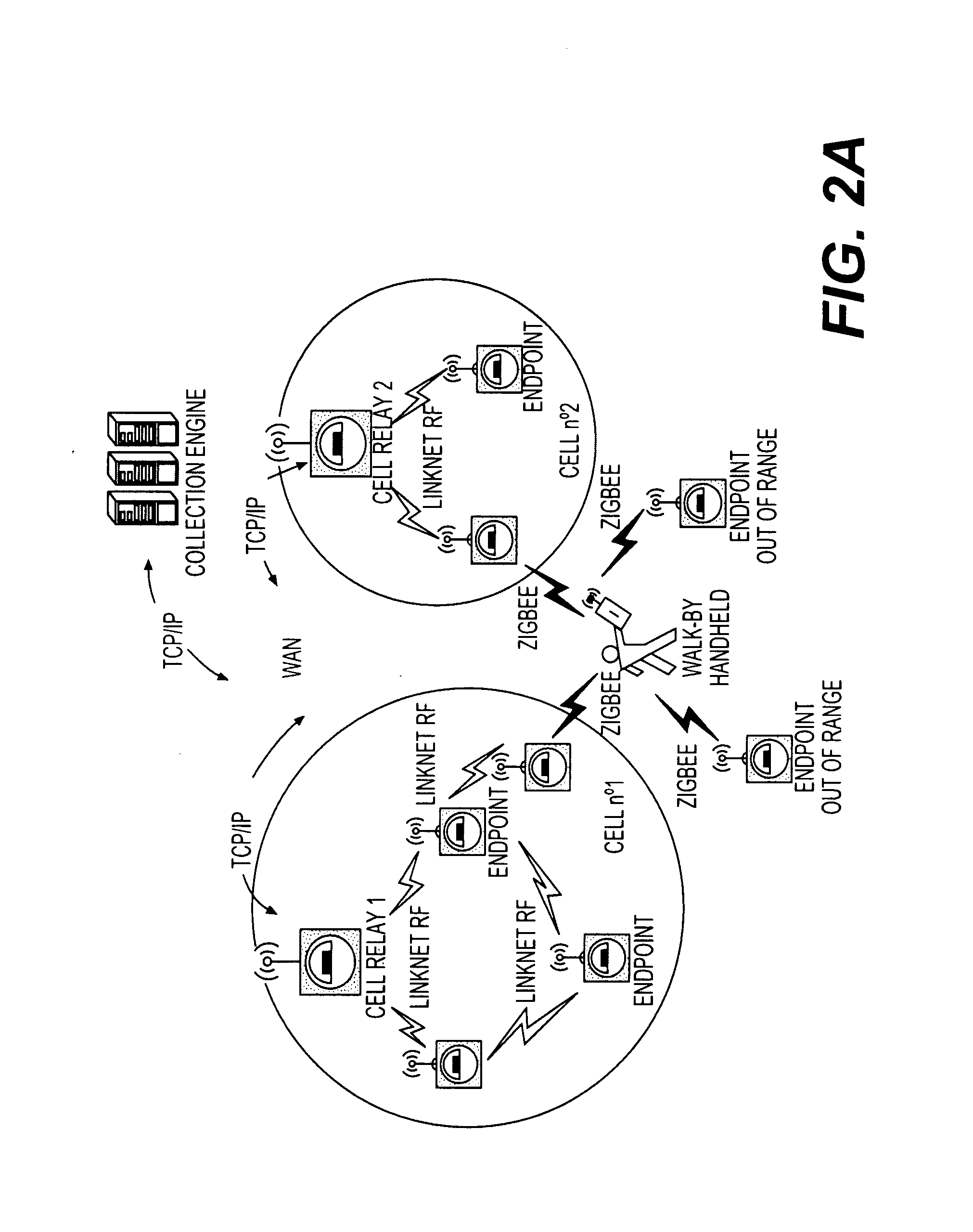
The present technology relates to protocols relative to utility meters associated with an open operational framework. More particularly, the present subject matter relates to protocol subject matter for advanced metering infrastructure, adaptable to various international standards, while economically supporting a 2-way mesh network solution in a wireless environment, such as for operating in a residential electricity meter field. The present subject matter supports meters within an ANSI standard C12.22 / C12.19 system while economically supporting a 2-way mesh network solution in a wireless environment, such as for operating in a residential electricity meter field, all to permit cell-based adaptive insertion of C12.22 meters within an open framework. Particular present features relate to the use of minimal propagation delay path to optimize a mesh network.

Description

PRIORITY CLAIMS [0001] This application claims the benefit of two previously filed U.S. Provisional Patent Applications entitled “METERING RF LAN PROTOCOL AND CELL / NODE UTILIZATION AND MANAGEMENT,” respectively assigned U.S. Ser. No. 60 / 845,056, as filed Sep. 15, 2006, and assigned U.S. Ser. No. 60 / 845,994, as filed Sep. 20, 2006, which are hereby incorporated herein by reference in their entireties for all purposes.FIELD OF THE INVENTION [0002] The present technology relates to protocols relative to utility meters associated with an open operational framework. More particularly, the present subject matter relates to protocol subject matter for advanced metering infrastructure, adaptable to various international standards, while economically supporting a 2-way mesh network solution in a wireless environment, such as for operating in a residential electricity meter field. BACKGROUND OF THE INVENTION [0003] The general object of metrology is to monitor one or more selected physical ph...

Claims


Application Information

Patent Timeline
Patent Type & Authority Applications(United States)
IPC IPC(8): H04L12/56G08C15/06H04L45/16H04L45/74H04W8/00H04W40/00H04W40/10H04W40/22H04W40/24H04W48/12H04W56/00H04W84/18
CPCG01D4/004H04B17/318H04L45/127H04W8/005H04W40/005H04W40/10H04W40/22H04W40/248H04W48/12H04W56/00H04W84/18Y02B90/242Y02B90/243Y04S20/322Y04S20/325G08C19/16Y02B90/246Y04S20/36Y04S20/42H04B1/7143H04B7/15H01L45/1273G01D4/006H04W56/0015H04W56/002Y02B90/20Y04S20/30H10N70/8418
Inventor PICARD, GILLES
Owner ITRON GLOBAL SARL
Learn More