Optical component and light emitting device using the same

a technology of optical components and light emitting devices, applied in the direction of optics, optical light guides, instruments, etc., can solve the problems of inability to obtain desired color from the lens, inability to retrieve efficiency, and wavelengths different from the wavelength of light exiting from the optical fiber, etc., to achieve convenient adjustment, prevent the production of chips and cracks, and satisfactory efficiency

Active Publication Date: 2008-03-27
NIPPON ELECTRIC GLASS CO LTD +1
View PDF13 Cites 85 Cited by
  • Summary
  • Abstract
  • Description
  • Claims
  • Application Information

AI Technical Summary

Benefits of technology

[0026]The light conversion member of the present invention is used in the optical component of the present invention, where the light conversion member is processed into a shape of any one of a circular cylindrical shape, a substantially circular truncated cone shape, a dome shape, and a spherical shape. By having the light conversion member as one of the circular cylindrical shape, the substantially circular truncated cone shape, the dome shape, and the spherical shape, production of chips and cracks is prevented when being inserted into the inner hole of the cap. Furthermore, the slip out of the light conversion member from the cap is easily prevented. Furthermore, if formed into a spherical shape, the optical axis is easily adjusted when sandwiched with the optical fiber holding member and the engagement part, and thus the optical fiber can be arranged at the portion of thickest thickness of the light conversion member, and the light exit from the optical fiber can be wavelength converted with satisfactory efficiency, and moreover, color tone variation caused by misalignment of the optical axis can be reduced. The color tune is easily adjusted by changing the diameter of the sphere through polishing.
[0027]The cap of the present invention is used in the optical component of the present invention, where the cap is made of metal. The reason being that metal has high heat conductivity compared to glass and ceramics, and that heat accumulated in the light conversion member can be diffused when converting the light exit from the optical fiber to light of a different wavelength. Furthermore, metal is easy to process, and the mechanical strength is high. The material...

Problems solved by technology

There arise problems such that the spherical lens may slip out, and that light exit from the ferrule may be reflected by the spherical lens instead of entering thereinto to lower light retrieving efficiency.
Th...

Method used


Image

  • Optical component and light emitting device using the same
  • Optical component and light emitting device using the same
  • Optical component and light emitting device using the same

Examples


second embodiment

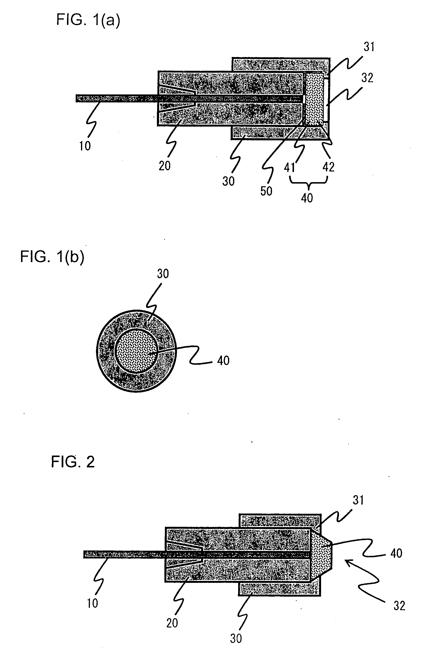
[0071]An optical component according to a second embodiment is to be described using the drawing. FIG. 2 is a schematic cross sectional view showing a configuration of the optical component according to the second embodiment of the present invention. As similar members are used, same reference numerals are denoted even if the shapes are different.

[0072]The optical component according to the second embodiment is substantially the same as that of the first embodiment other than the fact that the light conversion member 40 has a substantially circular truncated cone shape, and thus the description on the similar portions will not be repeated.

[0073]The light conversion member 40 has phosphors 42 contained in the glass 41. The light conversion member 40 has a substantially circular truncated cone shape, and thus has one part projecting out from the cap 30. The light retrieving efficiency thereby enhances. As the portion that shields the light exit from the optical fiber 10 is reduced, th...

third embodiment

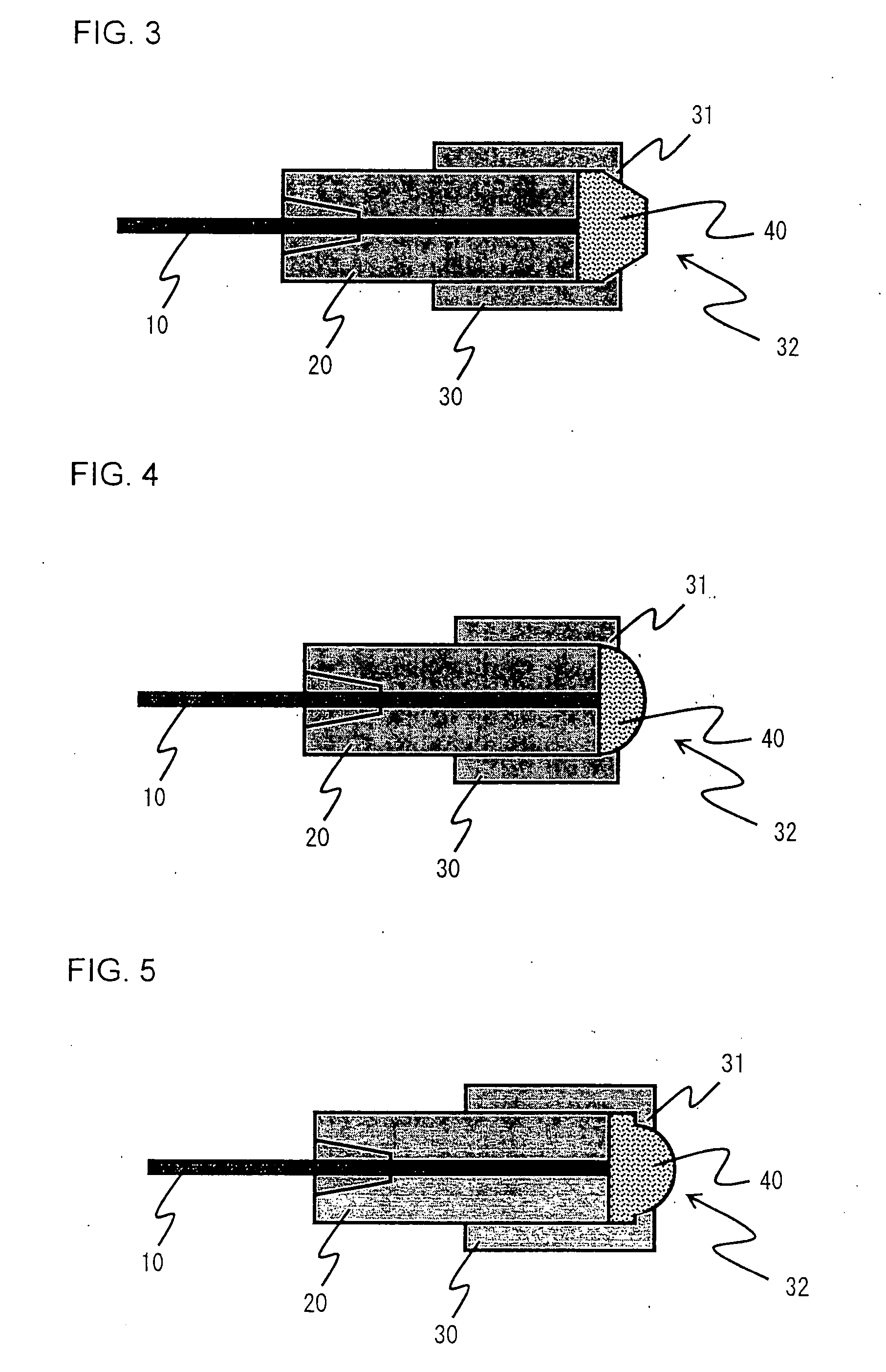
[0076]An optical component according to a third embodiment is to be described using the drawing. FIG. 3 is a schematic cross sectional view showing a configuration of the optical component according to the third embodiment of the present invention. As similar members are used, same reference numerals are denoted even if the shapes are different.

[0077]The optical component according to the third embodiment is substantially the same as that of the first embodiment other than the fact that the light conversion member 40 has a combined shape of a substantially circular truncated cone shape and a circular cylindrical shape, and thus the description on the similar portions will not be repeated.

[0078]The light conversion member 40 has a combined shape of substantially circular truncated cone and circular cylindrical shape, and has one part projecting out from the cap 30. A circular cylindrical shaped portion is further arranged on the substantially circular truncated cone shape to increase...

fourth embodiment

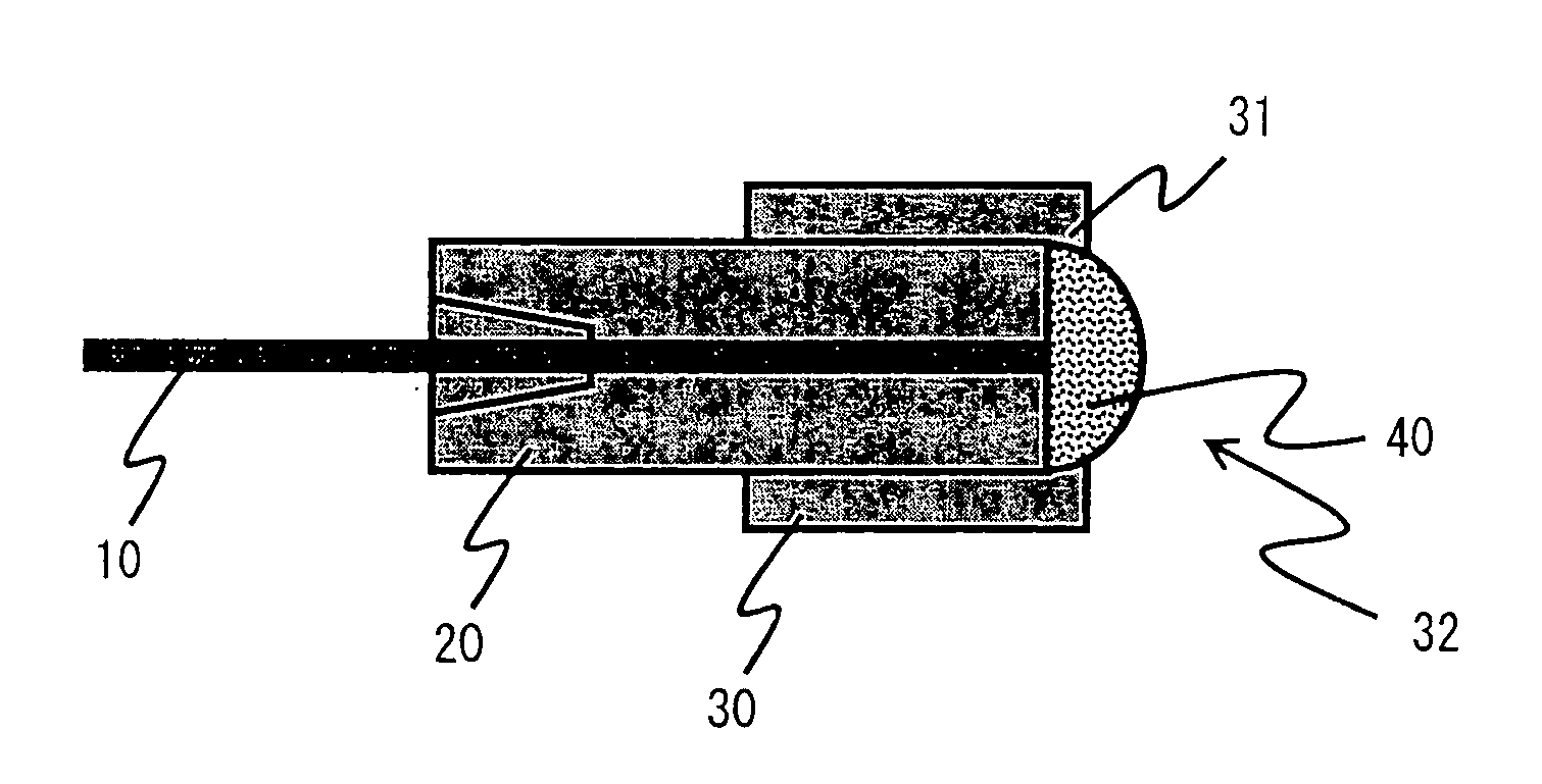
[0081]An optical component according to a fourth embodiment is to be described using the drawing. FIG. 4 is a schematic cross sectional view showing a configuration of the optical component according to the fourth embodiment of the present invention. As similar members are used, same reference numerals are denoted even if the shapes are different.

[0082]The optical component according to the fourth embodiment is substantially the same as that of the first embodiment other than the fact that the light conversion member 40 has a dome shape, and thus the description on the similar portions will not be repeated.

[0083]The light conversion member 40 has a dome shape and has one part projecting out from the cap 30. Due to such a dome shape, the light conversion member 40 has a lens effect, thereby enhancing the light collecting property. Furthermore, due to its dome shape, the light conversion member 40 is less likely to get caught by external obstructions. The term “dome shape” is used her...


PUM


Abstract

There is provided a light emitting device using an optical component capable of emitting light having a wavelength different from that of light exit from an optical fiber and obtaining light of high output, and capable of being easily attached to an end of the optical fiber. The optical component includes an optical fiber holding member for holding an optical fiber, a light conversion member, and a cap having an inner hole allowing the light conversion member and the optical fiber holding member to be inserted into and an engagement part with an opening for engaging inserted members at one end of the inner hole. The light conversion member inserted into the inner hole of the cap is fitted into the inner hole with the optical fiber holding member pressed against the engagement part. The opening of the engagement part is smaller than a maximum diameter of the light conversion member.

Description

BACKGROUND OF THE INVENTION[0001]1. Field of the Invention[0002]The present invention relates to an optical component capable of being attached to an end of an optical fiber, and a light emitting device using the optical component.[0003]2. Description of the Related Art[0004]Conventionally, there has been proposed a lamp for transmitting light from a light source to a disperser via a separator such as an optical fiber, and dispersing the light into a desired pattern or changing a color of the light (see e.g., Japanese Patent Publication No. 2003-515899).[0005]Also, a collimator is proposed, the collimator including a spherical lens and a ferrule for holding an optical fiber at a central shaft, a distal end of the optical fiber and a distal end of the ferrule being of a uniform surface, and the spherical lens and the ferrule being coaxially held so that the distal end of the optical fiber is positioned at a focus point of the spherical lens; wherein a first sleeve for holding the sph...

Claims


Application Information

Patent Timeline
IPC IPC(8): G02B6/36
CPCG02B6/4204G02B6/262
Inventor KADOMI, MASAAKIUMAYAHARA, YOSHIOFURUYAMA, TADAHITOIWAO, MASARUHAMA, ATSUTOMOSUGIYAMA, TAKAFUMIHAYASHI, YUKIHIROMORIZUMI, NAOTO
Owner NIPPON ELECTRIC GLASS CO LTD
Why Eureka
Try Eureka