Method and apparatus for producing cellulose resin film, and cellulose resin film and functional film

a technology of cellulose resin and cellulose resin film, which is applied in the direction of application, manufacturing tools, transportation and packaging, etc., can solve the problems of cellulose resins generating excessive heat due to friction, cellulose resins causing thermal degradation, and streak failure in cellulose resin films, etc., and achieve excellent optical properties

Inactive Publication Date: 2008-03-27
FUJIFILM CORP
View PDF6 Cites 21 Cited by
  • Summary
  • Abstract
  • Description
  • Claims
  • Application Information

AI Technical Summary

Benefits of technology

[0008]The present invention has been achieved in view of the above described circumstances, and takes as its objects the provision of a method and an apparatus for producing a cellulose resin film capable of suppressing the quality degradation of the film due to the heat generated in melt-kneading the cellulose resin and the generation of the streak failure on the cellulose resin film after completion of film formation, and allowing to obtain a cellulose resin film having excellent optical properties, and the provision of the cellulose resin film and a functional film.
[0010]According to the first aspect, in the extruder (hereinafter referred to as the single screw extruder), the mixing section in which kneading with a high shear force is conducted is disposed within a range where the molten resin does not generate excessive heat, and hence the cellulose resin can be sufficiently melt-kneaded without generating excessive heat, and thus a cellulose resin film being uniform and having excellent optical properties can be obtained.
[0012]According to the second aspect, in the single screw extruder, mixing is conducted in multiple separate stages without generating excessive heat in a single mixing stage, and hence the cellulose resin can be sufficiently melt-kneaded without generating excessive heat, and thus a cellulose resin film being uniform and having excellent optical properties can be obtained.
[0014]According to the third aspect, the gaps between the plurality of the mixing sections are made to be 1D or more, and hence the molten resin can be appropriately cooled between the multiple mixing stages to enable the suppression of the excessive heat generation of the molten resin.
[0016]According to the fourth aspect, mixing is conducted in multiple separate stages, and hence the excessive heat generation of the molten resin can be suppressed as compared to the case where melt-kneading is continuously conducted in a single stage of mixing section having the same total length as the plurality of the mixing sections.
[0025]According to the present invention, the quality degradation due to the heat generated when a cellulose resin is melt-kneaded and the generation of the streak failure on a cellulose resin film after completion of film formation can be suppressed, and thus a cellulose resin film having excellent optical properties can be obtained.

Problems solved by technology

However, conventional production methods have not been able to sufficiently melt resins and to sufficiently knead the molten resins in extruders, and hence cellulose resins are melted nonuniformly and fractions of cellulose resin crystals tend to remain to thereby cause a problem that streak failure occurs in cellulose resin films after completion of production.
On the other hand, there has been a problem such that when cellulose resins are melted and kneaded to an excessive extent in an extruder, the cellulose resins generate excessive heat due to friction to be thermally degraded.

Method used


Image

  • Method and apparatus for producing cellulose resin film, and cellulose resin film and functional film
  • Method and apparatus for producing cellulose resin film, and cellulose resin film and functional film
  • Method and apparatus for producing cellulose resin film, and cellulose resin film and functional film

Examples


example 1

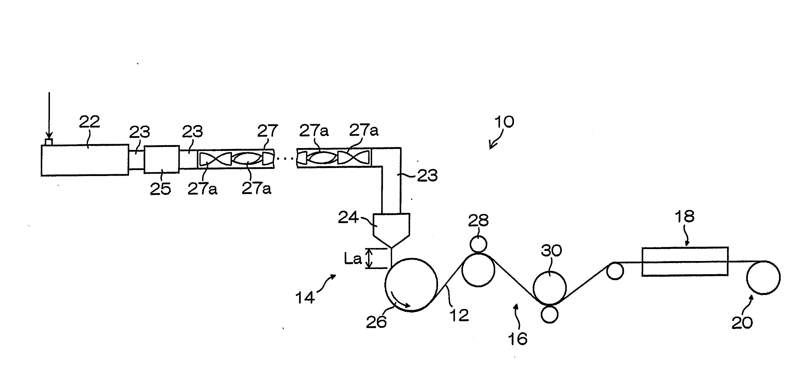
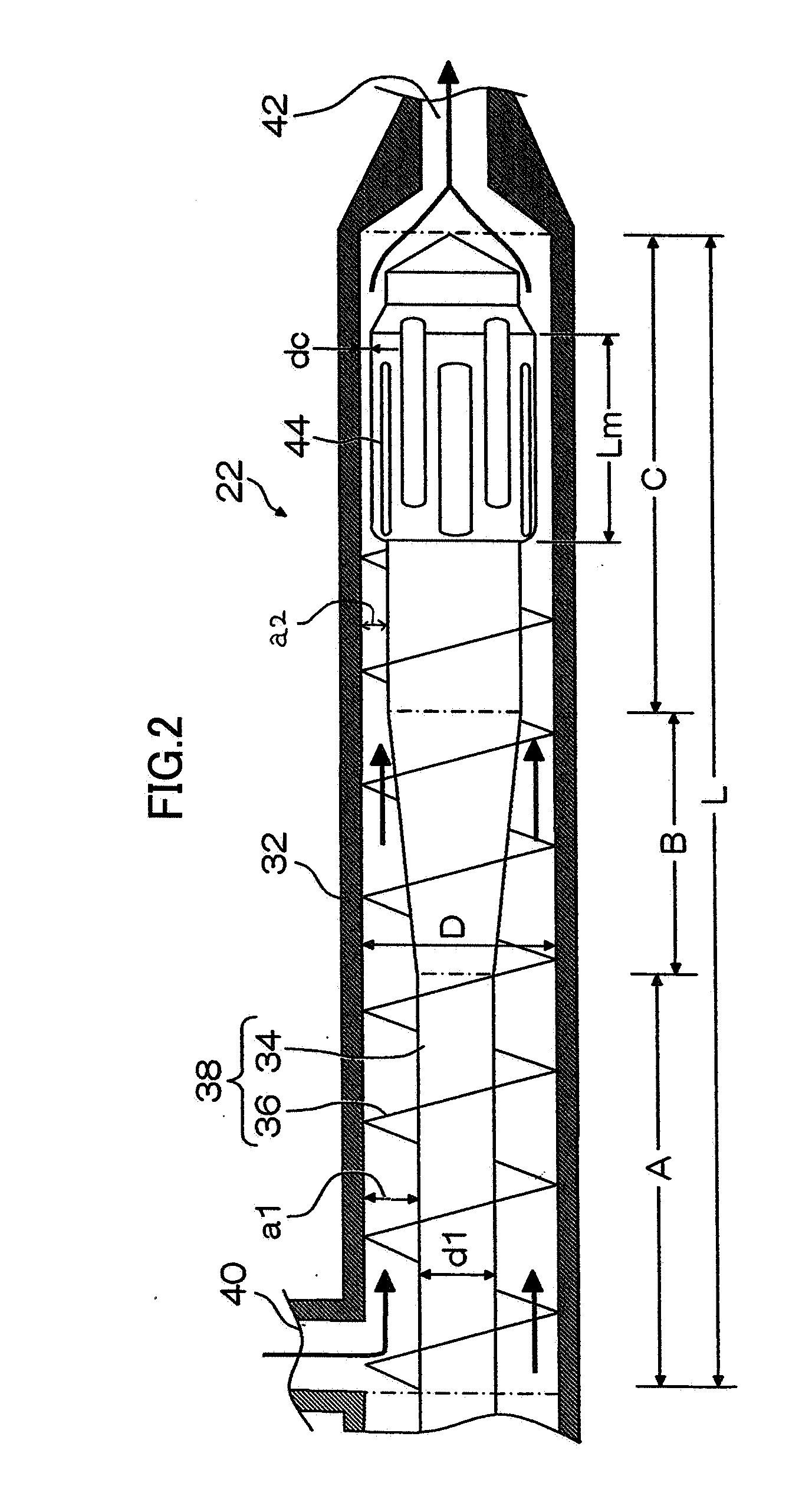
[0456]In the extruder 22, the groove depth in the feed section was set at 15 mm, the screw in the compression section was of a double flight type, and a mixing section 44 was provided on the exit side of the screw in the metering section. The mixing section 44 used was of a barrier type, had a extrusion direction length of 1D, and had the clearance dc of 1 mm between each of the leading ends of the mixing elements and the inner wall surface of the cylinder 32. The temperature in the feed section was set at 180° C. The temperature of the screw in the feed section was controlled by using a cast-in aluminum heater and by circulating oil in the screw.

[0457]The number of the stages of the static mixer 27 was 4, the temperature unevenness of the pipe communicatively connecting the extruder 22 to the die 24 was ±1° C. or less. The air gap between the cooling drum 26 and the die 24 was 90 mm.

example 2

[0458]Example 2 was the same as Example 1 except that on the exit side of the screw in the metering section in the extruder 22, a mixing section 44 (barrier type; extrusion direction length: 1D; clearance dc: 1 mm), a full flight (extrusion direction length: 2D) and another mixing section 44 (barrier type; extrusion direction length: 1D; clearance dc: 1 mm) were provided in this order.

example 3

[0459]Example 3 was the same as Example 1 except that on the exit side of the screw in the metering section in the extruder 22, a mixing section 44 (barrier type; extrusion direction length: 2D; clearance dc: 1 mm), a full flight (extrusion direction length: 3D) and another mixing section 44 (barrier type; extrusion direction length: 2D; clearance dc: 1 mm) were provided in this order.


PUM

PropertyMeasurementUnit
widthaaaaaaaaaa
depthaaaaaaaaaa
lengthaaaaaaaaaa

Abstract

According to an aspect of the present invention, in the extruder, the mixing section in which kneading with a high shear force is conducted is disposed within a range where the molten resin does not generate excessive heat, and hence the cellulose resin can be sufficiently melt-kneaded without generating excessive heat, and thus a cellulose resin film being uniform and having excellent optical properties can be obtained.

Description

BACKGROUND OF THE INVENTION[0001]1. Field of the Invention[0002]The present invention relates to a method and an apparatus for producing a cellulose resin film, in particular, a method and an apparatus for producing a cellulose resin film having a suitable quality for use in a liquid crystal display device.[0003]2. Description of the Related Art[0004]Thermoplastic resin films such as cellulose acylate resin films have been used as various optical films for liquid crystal display devices; for example, for practical purposes, thermoplastic resin films have hitherto been stretched along the longitudinal (lengthwise) direction and along the transverse (widthwise) direction of the films to develop the in-plane retardation (Re) and the thicknesswise retardation (Rth) to be used as retardation films in liquid crystal display elements for the purpose of widening viewing angle (see, for example, National Publication of International Patent Application No. 6-501040).[0005]A thermoplastic resi...

Claims


Application Information

Patent Timeline
Patent Type & Authority Applications(United States)
IPC IPC(8): C08J5/18B29C48/395B29C48/66B29C48/67
CPCB29C47/0021B29C47/60B29C47/605B29C47/62B29K2001/00Y10T428/24479C08J5/18C08J2301/02B29C47/362B29C47/622B29C47/6018B29K2001/12B29C48/08B29C48/362B29C48/53B29C48/565B29C48/645B29C48/66C08L1/02B29C41/00
Inventor UEDA, TADASHI
Owner FUJIFILM CORP
Why Eureka
Try Eureka