System and method for distributing and executing program code in a control unit network

a control unit network and program code technology, applied in the field of system and method for distributing and executing program, can solve the problems of not protecting against potential failure, unable to use the entire system, etc., and achieve the effect of avoiding a particularly large load avoiding the burden of the target unit, and being easy to implemen

Inactive Publication Date: 2008-03-27
ROBERT BOSCH GMBH
View PDF3 Cites 1 Cited by
  • Summary
  • Abstract
  • Description
  • Claims
  • Application Information

AI Technical Summary

Benefits of technology

[0010]One substantial point of the method according to the present invention is that it is constructed particularly simply, and is thus safe. Since it can also be added on to the usual communications protocols in vehicle electrical systems, such as CAN (controller area network) bus, it is also easy to implement and therefore cost-effective.
[0011]It is provided in one advantageous specific embodiment that it is first determined whether the target control unit has free resources for executing the program code, and if this is the case, these free resources are reserved for executing the transmitted code. Because of this, one does not have to establish a communications partner right from the beginning, for every failure-protected control unit. To the contrary, because of the determination of free resources, a dynamic distribution of programs or program portions can be achieved, to control units which will have suitable resources when needed.
[0012]An advantage is created, in addition, if a program that is reduced in comparison to its full functional volume is transmitted by the source control unit to the target control unit. This avoids a particularly great load of the target unit, or rather, even slight resources can still be used, without having to limit safety-relevant core functions of the program.
[0013]One further advantage is created if programs and / or program portions having comparatively low safety relevance are shut down on the target control unit. That is how the target control unit can be utilized for the concentrated execution of functions of the highest priority.

Problems solved by technology

In spite of that, such an entire system can become unusable if one of the units fails, for instance, because of a hardware defect.
This permits a central management and modification of the individual functional units of the vehicle, to be sure, but it does not protect from their potential failure.

Method used


Image

  • System and method for distributing and executing program code in a control unit network
  • System and method for distributing and executing program code in a control unit network

Examples


Embodiment Construction

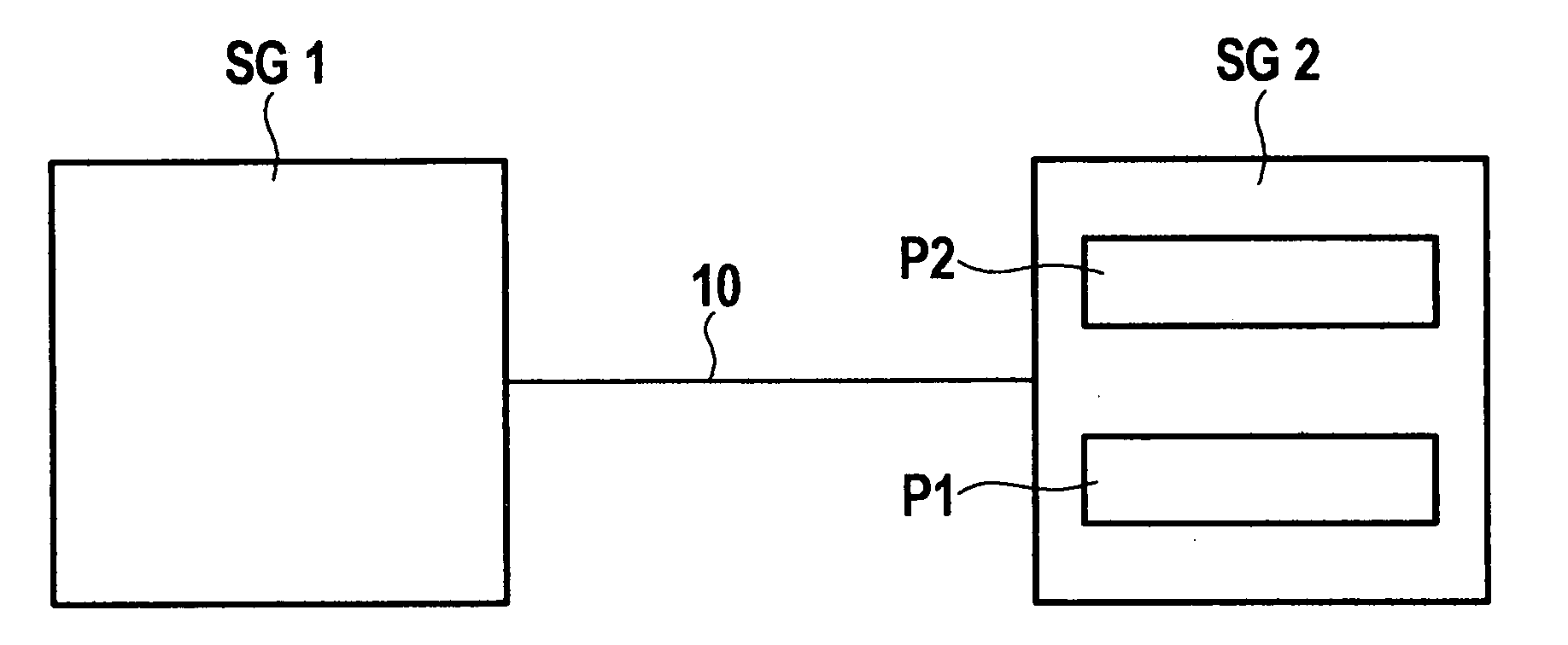
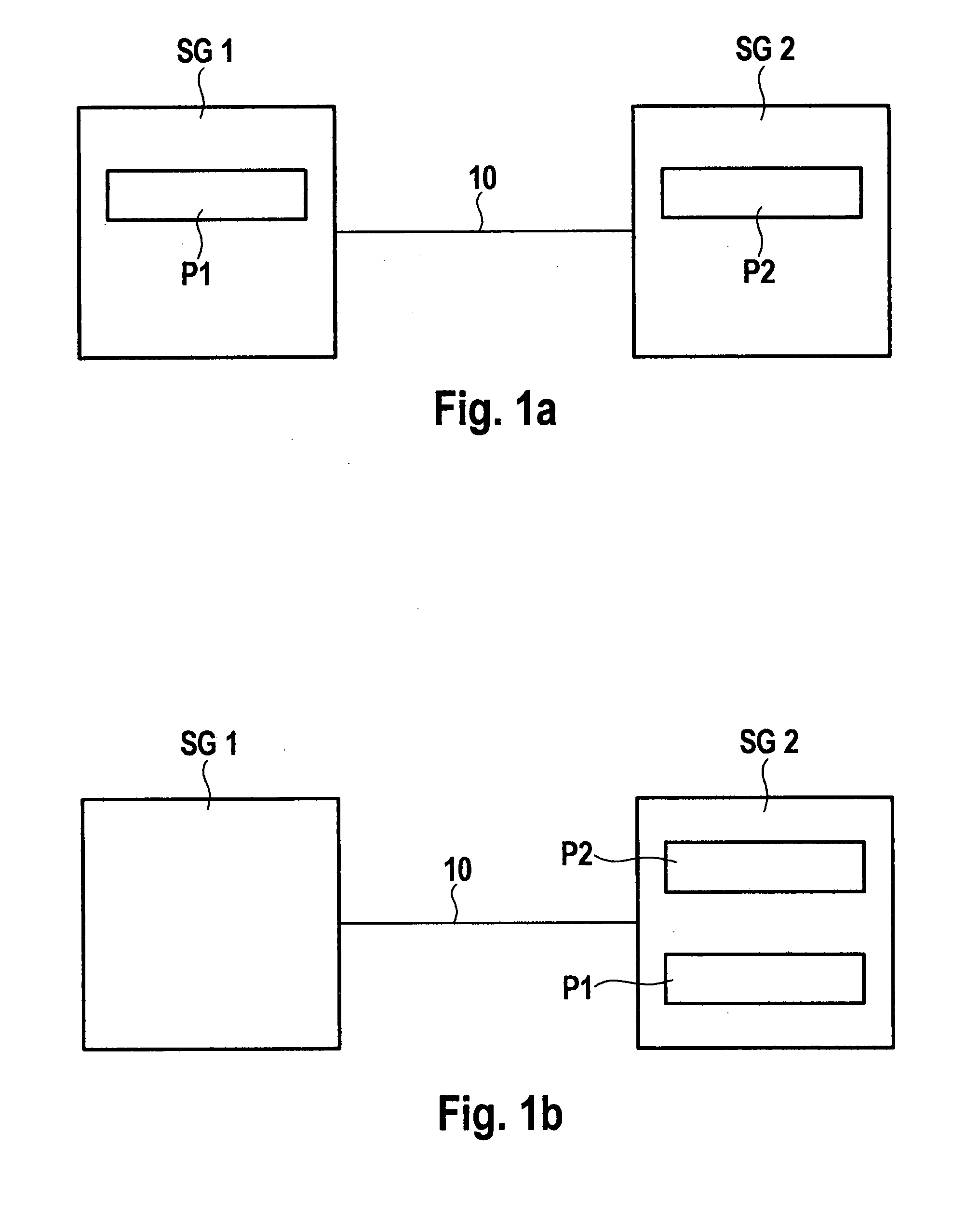
[0016]FIG. 1a shows a schematic representation of two intact control units SG1 and SG2 that are connected to each other via a network 10. Network 10 is designed as a data bus and a program bus via which control units SG1 and SG2 are able to exchange data portions and program software portions. Control unit SG1, for instance, is responsible for the operation of an antilock system and unit SG2 for engine control.

[0017]The functioning of these applications is shown by a program code P1 and P2, which are executed on units SG1 and SG2, respectively. Now, if a hardware defect is detected in control unit SG1, calculator resources in unit SG2 that are still free are reserved, program code P1 of unit SG1 is transmitted via network 10 and brought to execution on unit SG2.

[0018]FIG. 1b shows the configuration of FIG. 1a, in which the function of a defective control unit SG1 is portrayed by the other control unit SG2. Program code P1 of unit SG1 was transmitted to unit SG2, in this context, and...


PUM


Abstract

A system and a method for distributing and executing program code in a control unit network, in which at least one of the units is able to detect a defect in its hardware and is able to transmit its code to at least one other control unit in the network, the transmitted code being executable on the target control unit.

Description

BACKGROUND INFORMATION [0001]Up to now, control units have been installed, for instance, in motor vehicles which are designed corresponding to particularly predefined and limited functions. In normal operation, these units run only under partial load. However, many of them are dimensioned so that they could manage higher (even peak) loads. Moreover, many of these units are connected to one another via a network, for the exchange of data. In spite of that, such an entire system can become unusable if one of the units fails, for instance, because of a hardware defect.[0002]A system for controlling / regulating the operating sequences in a motor vehicle is described in German Patent No. DE 100 27 006. It has a central memory in which all programs necessary for this are stored. At the start of the system, the control units load the required programs into their working memories via memory accesses. This permits a central management and modification of the individual functional units of the...

Claims


Application Information

Patent Timeline
Patent Type & Authority Applications(United States)
IPC IPC(8): G06F9/46
CPCG05B19/042G05B2219/2637G05B2219/23295G05B2219/23004
Inventor KUTTENBERGER, ALFRED
Owner ROBERT BOSCH GMBH
Why Eureka
Try Eureka