Flowmeter verification on a magnetic flowmeter

a magnetic flowmeter and flowmeter technology, applied in the field of magnetic flowmeter verification, can solve the problems of expensive procedures, cumbersome training of technicians, and inability to verify flow data,

Active Publication Date: 2008-04-03
MICRO MOTION INC
View PDF10 Cites 19 Cited by
  • Summary
  • Abstract
  • Description
  • Claims
  • Application Information

AI Technical Summary

Problems solved by technology

These procedures are expensive, cumbersome and require a trained technician to perform the testing.

Method used


Image

  • Flowmeter verification on a magnetic flowmeter
  • Flowmeter verification on a magnetic flowmeter
  • Flowmeter verification on a magnetic flowmeter

Examples


Embodiment Construction

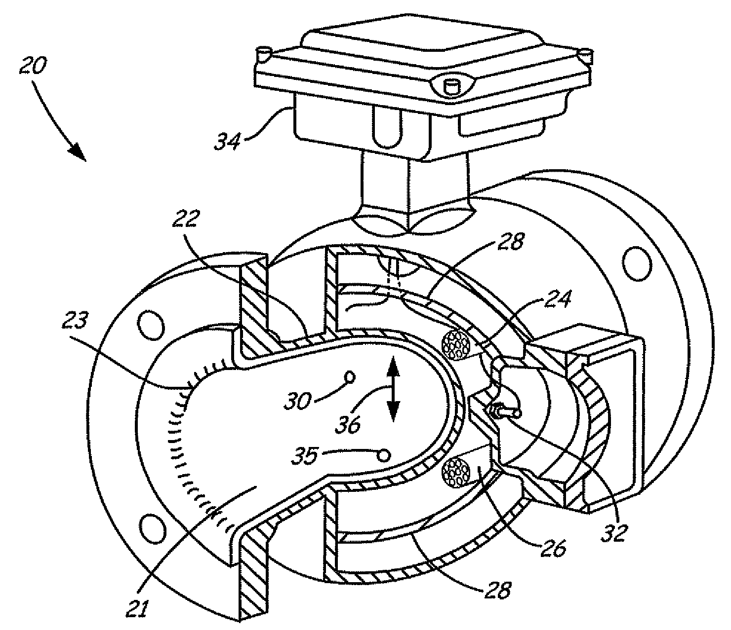
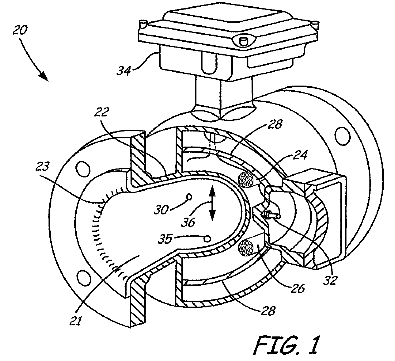
[0010]The present invention provides a method and apparatus for verifying operation of a flowtube or magnetic flowmeter with circuitry provided internal to the meter. This configuration does not require the process to be shut down and the flowtube removed from service, and does not require separate or otherwise additional equipment or trained personnel to perform the testing.

[0011]In the magnetic flowmeter, verification circuitry is provided which measures a parameter of the magnetic flowtube and / or transmitter circuitry associated with the flowmeter. The verification circuitry can be configured to measure a parameter of the flow tube including related electronic circuitry. The circuitry responsively provides a verification output based upon a comparison of the measured parameter and a stored value related to a nominal value of the parameter. The comparison can be, for example, based upon threshold limits, change over time, etc. More than one parameters can be measured and verified ...


PUM


Abstract

A magnetic flowmeter is provided including a magnetic flowtube arranged to receive a flow of process fluid. The magnetic flowtube includes a drive coil and at least one sense electrode. Measurement circuitry is coupled to the flowtube and is configured to provide a drive signal to the drive coil and measure flow of process fluid through the flow tube based upon an output from the sense electrode. A memory contains a stored value related to a nominal parameter of the flowtube. Verification circuitry is arranged to measure a parameter of the magnetic flowtube and responsively provide a verification output related to operation of the magnetic flowmeter based upon a comparison of the measured parameter and the stored value.

Description

[0001]The present application is based on and claims the benefit of U.S. provisional patent application Ser. No. 60 / 848,314, filed Sep. 29, 2006, the content of which is hereby incorporated by reference in its entirety.BACKGROUND OF THE INVENTION[0002]The present invention relates to the process measurement and control industry. More specifically, the present invention relates to magnetic flowmeters of the type used to measure flow of a process fluid.[0003]Magnetic flow meters are used to measure flow of a conductive process fluid through a flowtube. The conductive fluid flows past an electromagnet and electrodes. In accordance with Faraday's law of electromagnetic induction, an electromotive force (EMF) is induced in the fluid due to an applied magnetic field. The EMF is proportional to the flow velocity of the fluid. The electrodes are positioned in the flowtube to make electrical contact with the flowing fluid. The electrodes sense the EMF that is magnetically induced in the flui...

Claims


Application Information

Patent Timeline
Patent Type & Authority Applications(United States)
IPC IPC(8): G01F1/60
CPCG01F25/0007G01F1/60G01F25/10
Inventor GRABER, WILLIAM F.FOSS, SCOT R.SCHULZ, ROBERT K.
Owner MICRO MOTION INC
Why Eureka
Try Eureka