
Capacitive electromagnetic flow signal converter

A signal converter, electromagnetic flow technology, applied in the application of electromagnetic flowmeters to detect fluid flow, volume/mass flow generated by electromagnetic effects, instruments, etc., can solve problems such as interference detection circuits, measurement accuracy cannot be further improved, and achieve work Uniform magnetic field, prevent leakage, and improve the effect of measurement accuracy

Inactive Publication Date: 2014-09-24
UNIV OF ELECTRONICS SCI & TECH OF CHINA
View PDF4 Cites 21 Cited by
  • Summary
  • Abstract
  • Description
  • Claims
  • Application Information

AI Technical Summary

Problems solved by technology

[0012] However, the existing capacitive electromagnetic flowmeter also has certain defects, mainly the sensitivity needs to be improved, and the magnetic field leaked from the excitation device will interfere with the detection circuit in the external space, so that the measurement accuracy cannot be further improved

Method used


Image

  • Capacitive electromagnetic flow signal converter
  • Capacitive electromagnetic flow signal converter
  • Capacitive electromagnetic flow signal converter

Examples


Embodiment Construction

[0040] Specific embodiments of the present invention will be described below in conjunction with the accompanying drawings, so that those skilled in the art can better understand the present invention. It should be noted that in the following description, when detailed descriptions of known functions and designs may dilute the main content of the present invention, these descriptions will be omitted here.

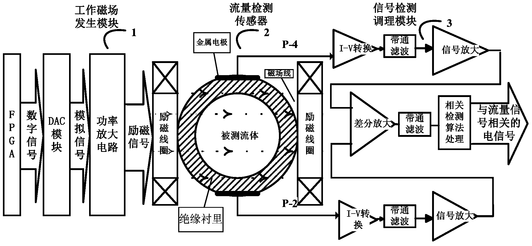
[0041] In this example, if figure 1 As shown, the capacitive electromagnetic flow signal converter of the present invention consists of three parts: a working magnetic field generating module 1 , a flow detection sensor 2 and a signal detection and conditioning module 3 .

[0042] 1. Working magnetic field generating module

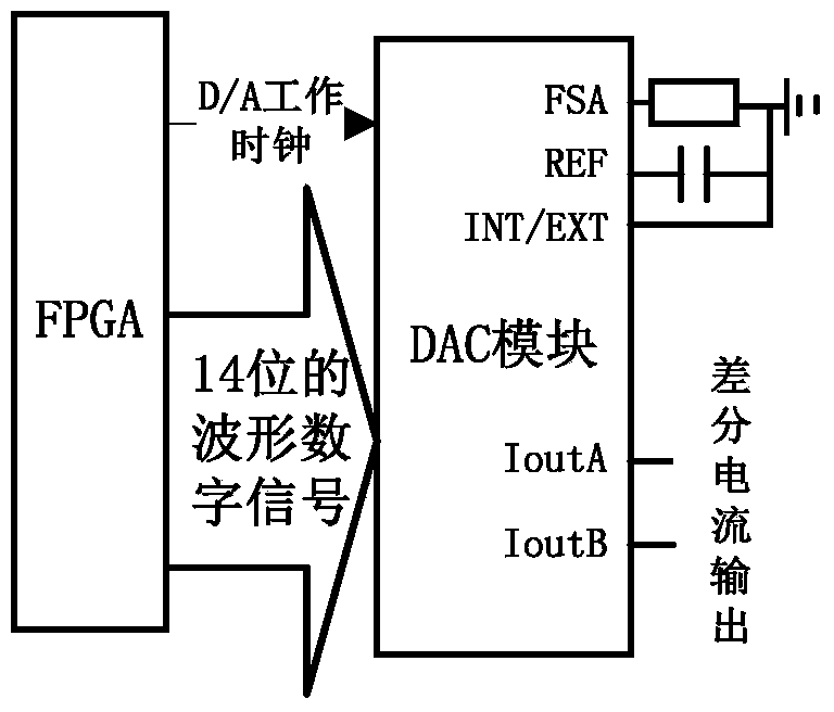
[0043] The working magnetic field generation module 1 is composed of two parts: the excitation signal generation circuit and the excitation device. Its function is to generate a sine wave excitation signal with a frequency of 150 Hz by the excitation ...


PUM


Abstract

The invention discloses a capacitive electromagnetic flow signal converter. Two E-shaped magnetic yokes are adopted and are combined together face to face at the position of an opening so as to form a closed loop, and therefore working magnetic field leakage can be effectively prevented. Meanwhile, according to the two E-shaped magnetic yokes which are formed by stacking E-shaped silicon steel sheets, excitation coils are wound on stretching-out portions in the middles of the E-shaped magnetic yokes, two Helmholtz coils are connected in series and arranged coaxially, and the Helmholtz coils are identical in shape, size and number of turns. After excitation signals are input into the Helmholtz coils which are connected in series, an even working magnetic field with the magnetic field intensity changing along with excitation sinusoidal signals can be generated between excitation devices, due to the fact that the generated working magnetic field is even, the magnetic permeability of the silicon steel sheets is very good, the magnetic field at the position of a measuring pipe is very strong, the sensitivity of flow detection is also improved, so that fluid flow can be effectively converted into electric signals to be output, and the fluid flow measuring accuracy of a capacitive electromagnetic flow meter is further improved.

Description

technical field [0001] The invention belongs to the technical field of flow measurement, and more specifically relates to a capacitive electromagnetic flow signal converter. Background technique [0002] There are many kinds of flow detection methods, among which there are more than ten kinds with more mature technologies. There is no uniform classification standard for flow measurement methods. Classification according to the measured object can be divided into open channel and closed pipeline. If classified according to the principle of the instrument, it can be divided into magnetoelectric type, piezoelectric type, etc. The measured parameters can be classified into direct and indirect. Commonly used flow measurement methods include vortex, differential pressure, ultrasonic, mass flow and electromagnetic flow measurement. [0003] Electromagnetic flowmeter is an instrument for flow detection and measurement based on Faraday's law of electromagnetic induction. The basic...

Claims


Application Information

Patent Timeline
IPC IPC(8): G01F1/58G01N15/00
Inventor 赵辉詹惠琴杨红宇古军李云霞
Owner UNIV OF ELECTRONICS SCI & TECH OF CHINA
Learn More