Fan Module motor mont arms with shape optimization

a technology of motor mounting and fan module, which is applied in the direction of machines/engines, manufacturing tools, liquid fuel engines, etc., can solve the problems of affecting the airflow of the engine compartment, and general perception of unpleasant noise, so as to reduce the interference of in-vehicle air flow patterns

Inactive Publication Date: 2008-04-03
SIEMENS VDO AUTOMOTIVE INC
View PDF11 Cites 10 Cited by
  • Summary
  • Abstract
  • Description
  • Claims
  • Application Information

AI Technical Summary

Benefits of technology

[0007]An object of the invention is to fulfill the need referred to above. In accordance with the principles of the present invention, this objective is achieved by providing a fan module for mounting a fan of a vehicle. The fan module includes a base, a motor mount constructed and arranged to mount a fan motor thereto, and a plurality of connecting elements each having a radial axis and an axis generally transverse to the radial axis. Each connecting element extends radially between the base and the motor mount, coupling the motor mount to the base. At least one connecting element is oriented about the radial axis thereof in a manner different from an orientation of at least one other connecting element with respect to its radial axis so that the orientation of the at least one connecting element generally reduces interference with in-vehicle air flow patterns.

Problems solved by technology

These connecting elements maintain structural rigidity but create an obstacle to the air path produced by the fan.
These obstacles in the path of the airflow then create an acoustic disturbance that leads to a noise generally perceived as unpleasant.
In addition, the airflow in the engine compartment is highly un-symmetric in the tangential direction because several engine accessory components block the inlet and outlet air path to the fan.
This U-shape provides excellent structural performance; however, the shape is acoustically detrimental.
However, the shape of the element 10 provides weak structural performance.

Method used


Image

  • Fan Module motor mont arms with shape optimization
  • Fan Module motor mont arms with shape optimization
  • Fan Module motor mont arms with shape optimization

Examples


Embodiment Construction

[0026]A fan has the purpose to move a substance of gaseous state. A multiple number of fan blades fixed rigidly to a fan hub and surrounded by a ring produces air flow when rotating. The fan produces air at very high flow rates even when the wake of the fan is highly restricted by obstacles. Therefore, such a fan is highly suited for automotive engine cooling applications where the wake of the fan is blocked by the automotive engine or other components.

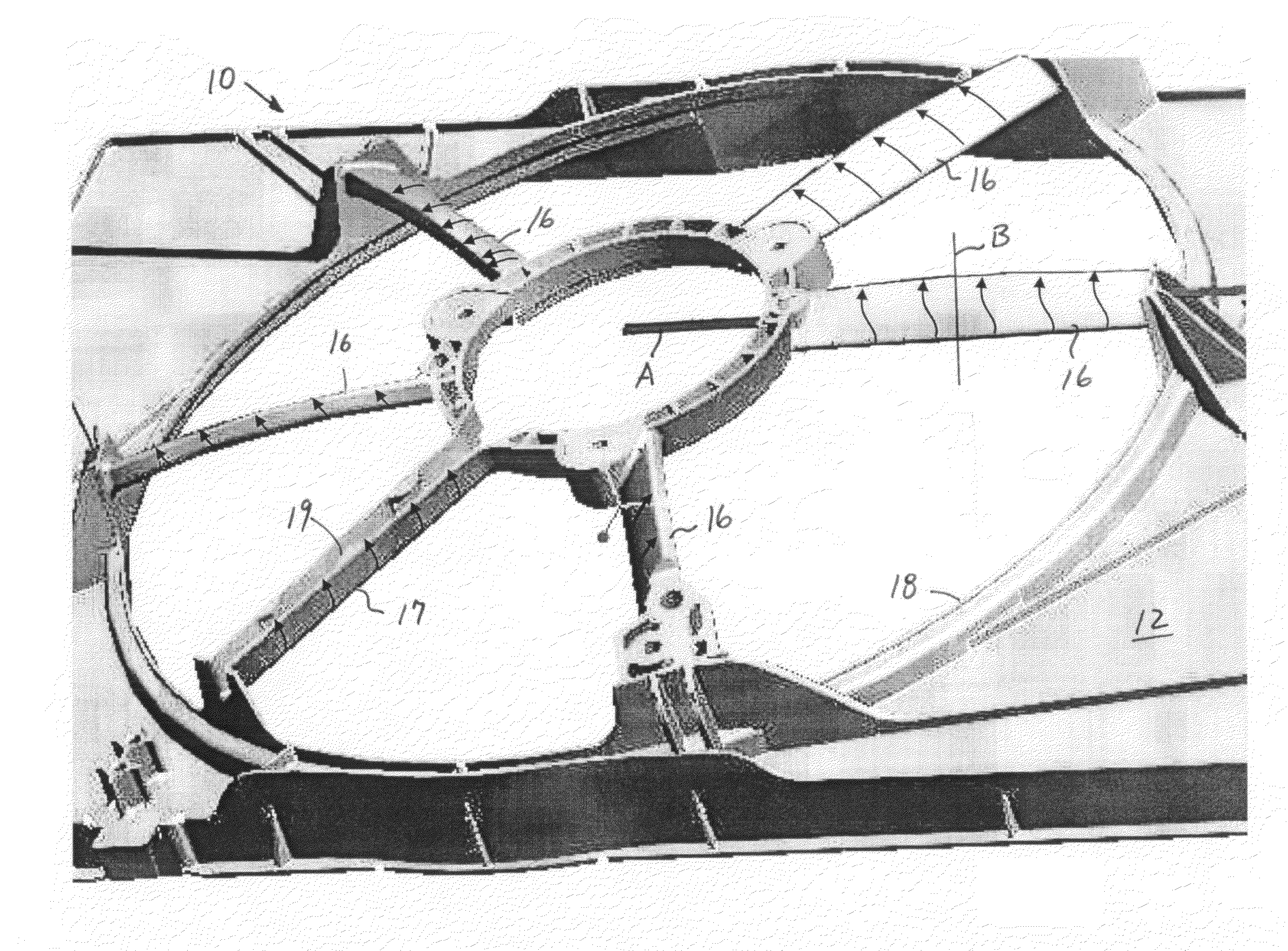
[0027]The fan is coupled to a shaft of a motor. The motor (not shown) is mounted to a fan module or shroud 10 (FIG. 3). The module 10 includes a generally rectangular base 12, a motor mount 14, for mounting the motor thereto, and a plurality of motor mount arms or connecting elements 16 connecting the motor mount 14 to the base 12. The base 12 includes an opening for receiving a fan (not shown) in the conventional manner. A member 17 between the base 12 and motor mount 14 includes a trough 19 for receiving the wires for powering the m...


PUM

PropertyMeasurementUnit
velocityaaaaaaaaaa
non-symmetrical elliptical shapeaaaaaaaaaa
shapeaaaaaaaaaa

Abstract

A fan module (10) for mounting a fan of a vehicle includes a base (12), a motor mount (14) constructed and arranged to mount a fan motor thereto, and a plurality of connecting elements (16) each having a radial axis and an axis generally transverse to the radial axis. Each connecting element extends radially between the base and the motor mount, coupling the motor mount to the base. At least one connecting element is oriented about the radial axis thereof in a manner different from an orientation of at least one other connecting element with respect to its radial axis so that the orientation of the at least one connecting element generally reduces interference with in-vehicle air flow patterns.

Description

[0001]This application claims the benefit of the earlier filing date of U.S. Provisional Application No. 60 / 827,268, filed on Sep. 28, 2006, which is incorporated by reference herein in its entirety.FIELD OF THE INVENTION[0002]This invention relates to fan modules for engine cooling of a vehicle and, more particularly, to the orientation and shape of the motor mounting or connecting elements of a shroud of fan module.BACKGROUND OF THE INVENTION[0003]An electric motor drives a fan that moves air with the multiple fan blades. The typical blade configuration ensures that the blades extend from the root (fan hub) and stretch radially outward. The fan supplies the required air mass necessary for cooling of an engine of a vehicle. The electric motor drive must be mounted to a fix point relative to the vehicle in the engine compartment. If there is ample space for installation of a fan module in the engine compartment, then a multiplicity of guide vane elements or motor mounting elements a...

Claims


Application Information

Patent Timeline
Patent Type & Authority Applications(United States)
IPC IPC(8): F01P5/06B29C45/14F04D29/40
CPCB29C45/00F01P5/06Y10T29/49826F04D29/544F04D29/526
Inventor HAVEL, BRIAN
Owner SIEMENS VDO AUTOMOTIVE INC
Why Eureka
Try Eureka