

Methods of forming a laryngeal mask
a technology of laryngeal mask and laryngeal tube, which is applied in the direction of respirators, other domestic articles, breathing protection, etc., can solve the problems of more expensive and slower than other molding techniques, the point of potentially compromised stability,
- Summary
- Abstract
- Description
- Claims
- Application Information
AI Technical Summary
Benefits of technology
Problems solved by technology
Method used
Image

Examples
Embodiment Construction
)
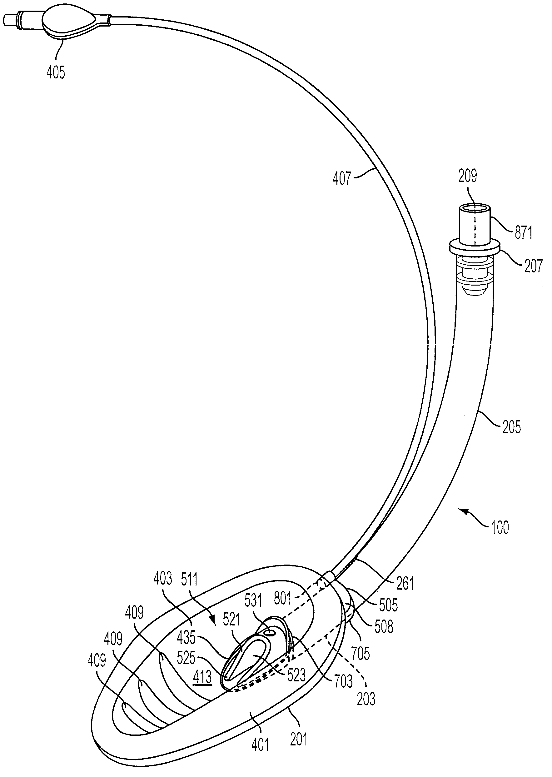
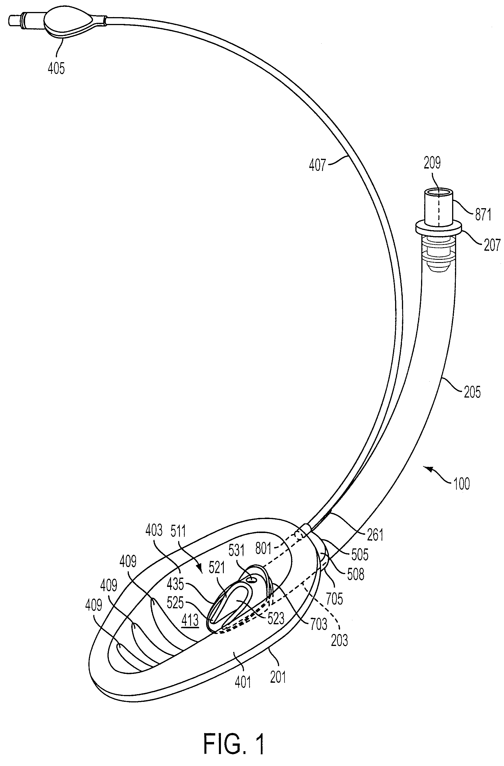
[0036]The following detailed description illustrates by way of example and not by way of limitation. Described herein, among other things, are embodiments of methods for constructing supraglottic airways using blow molding. Specifically, the supraglottic airway has a shield (201) constructed as a single blow-molded structure to allow for improved ease of assembly and speed of manufacture. While the supraglottic airway described herein incorporates certain features in the shape and features of the shield (201) for improved placement in the airway, it should be recognized that these features are not required and the techniques of manufacture can be used on airways of other shapes and forms.
[0037]FIG. 1 provides for an embodiment of a supraglottic airway in the form of removable laryngeal mask airway (100). This mask (100) is chosen as an exemplary form of supraglottic airway to simply demonstrate how the systems and methods of construction and assembly discussed herein can be used. I...
PUM
| Property | Measurement | Unit |
|---|---|---|
| length | aaaaa | aaaaa |
| area | aaaaa | aaaaa |
| thick | aaaaa | aaaaa |
Abstract
Description
Claims
Application Information