Damper assembly

a technology of suspension system and sprung mass, which is applied in the direction of shock absorbers, machine supports, transportation and packaging, etc., can solve the problems of disproportionate acceleration of sprung mass, easy transmission of unsprung suspension displacement by the sprung mass, and virtually lossless, and achieves low impedance and damping. , the effect of small displacemen

Inactive Publication Date: 2008-04-03
GM GLOBAL TECH OPERATIONS LLC
View PDF37 Cites 2 Cited by
  • Summary
  • Abstract
  • Description
  • Claims
  • Application Information

AI Technical Summary

Benefits of technology

[0004]As the wheel assembly of the vehicle encounters road inputs, the suspension system undergoes compression (ounce) and extension (rebound) strokes. Current dampers in strut type suspension systems, exhibit effects that suggest a strong influence of stiction. The damper carries a radial load induced by reaction of static and dynamic forces in the suspension. This radial load binds the damper rod and tube at the rod guide and piston interfaces. The bind results in a relatively stiff suspension member because the damper rod ceases to freely move within the tube, defeating the advantageous effects of the displacement of the internal fluid. Under such conditions, the damper readily transmits unsprung suspension displacement, virtually lossless (as if it were elastic). Dynamic forces at the reaction interfaces of the vehicle body are much larger than desired, ultimately producing disproportionately large accelerations of the sprung mass.
[0005]As a result, it is desirable to provide a new damper assembly for a suspension system of a vehicle that is in series with an existing damper of a vehicle. It is also desirable to provide a damper assembly for a suspension system of a vehicle that provides damping and is stiction free. It is further desirable to provide a damper assembly for a suspension system of a vehicle that simultaneously reacts the relatively large static, quasi-static, and dynamic radial and bending loads without binding the damper. Therefore, there is a need in the art to provide a damper assembly for a suspension system of a vehicle that meets at least one of these desires.SUMMARY OF THE INVENTION
[0006]Accordingly, the present invention is a damper assembly for a suspension system of a vehicle. The damper assembly includes a housing adapted to be mounted to one end of a strut in the suspension system. The housing has a chamber with fluid therein. The damper assembly also includes at least one diaphragm extending across the chamber to react with the fluid, to be compliant at relatively small displacements, and to be rigid at relatively large displacements.
[0007]One advantage of the present invention is that a damper assembly is provided for a suspension system of a vehicle that is stiction free by using elastomeric or small displacement elastic members. Another advantage of the present invention is that the damper assembly provides hydraulic damping. Yet another advantage of the present invention is that the damper assembly uses elastomeric or elastic reactions under small displacements to simultaneously react the relatively large static radial and bending loads that usually bind a conventional damper. Still another advantage of the present invention is that the damper assembly acts in series with the existing damper for low amplitude dynamic displacements, providing relatively low impedance and required damping. A further advantage of the present invention is that the damper assembly acts in series with the existing damper, and at larger displacements, after the travel limits are engaged, is dynamically relatively rigid.

Problems solved by technology

Under such conditions, the damper readily transmits unsprung suspension displacement, virtually lossless (as if it were elastic).
Dynamic forces at the reaction interfaces of the vehicle body are much larger than desired, ultimately producing disproportionately large accelerations of the sprung mass.

Method used


Image

  • Damper assembly
  • Damper assembly
  • Damper assembly

Examples


Embodiment Construction

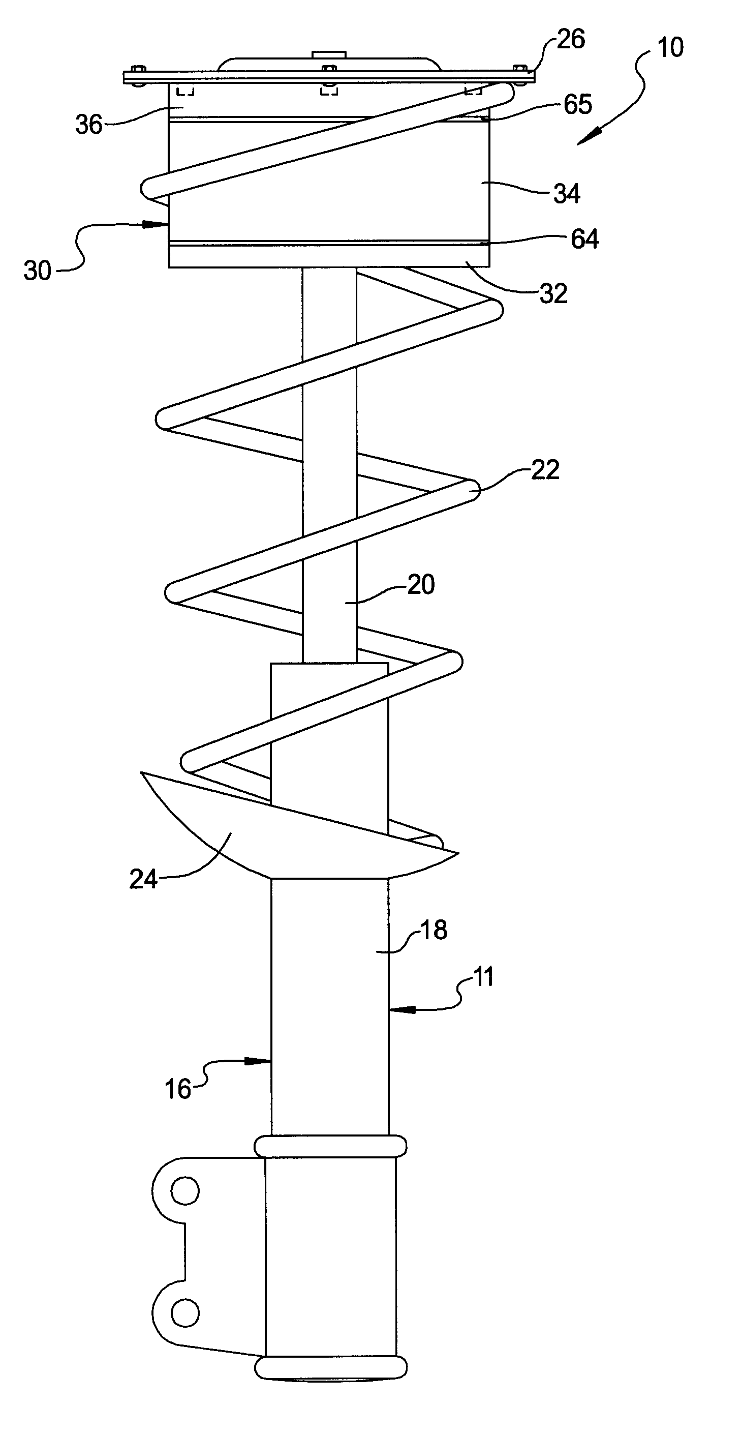
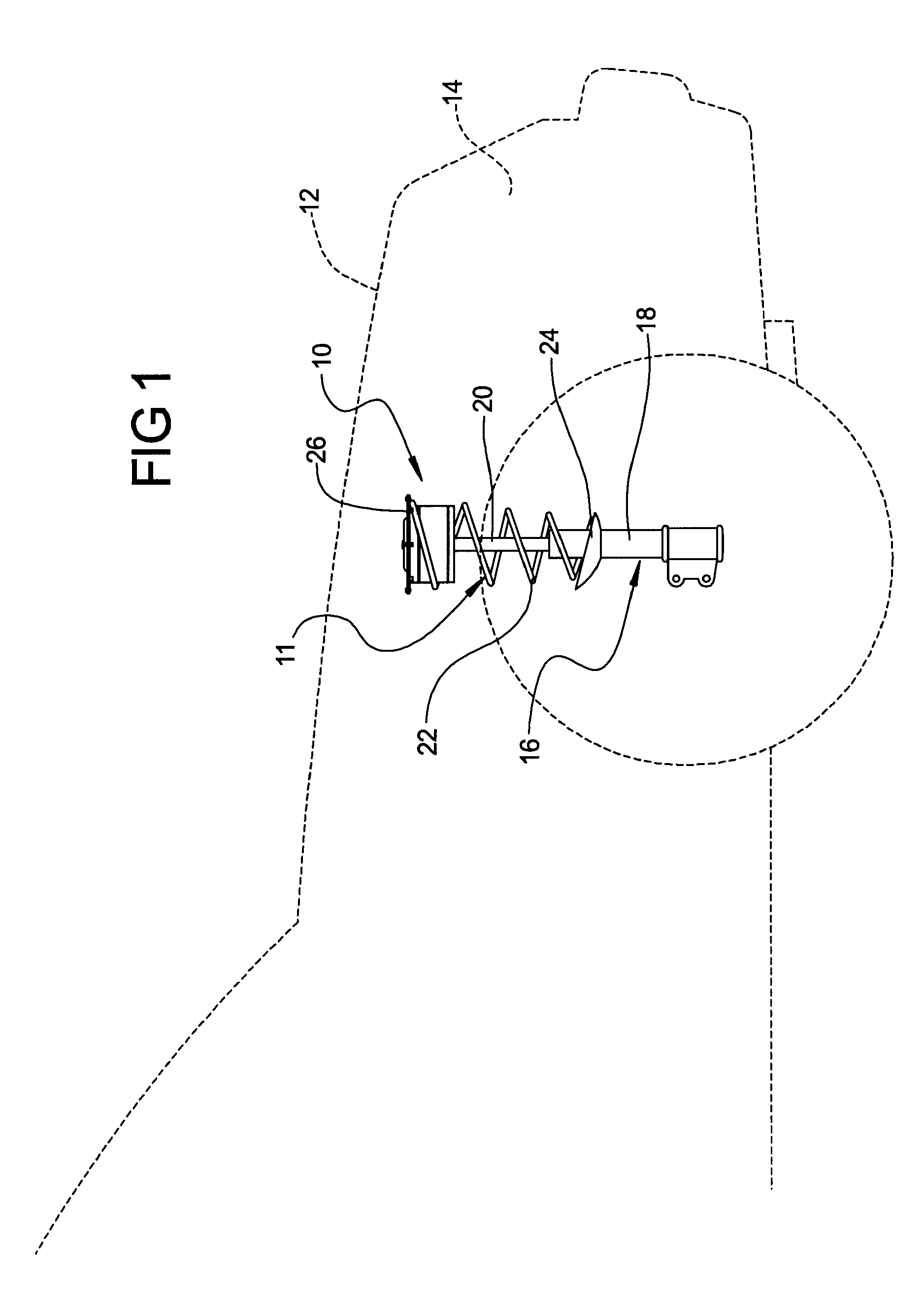
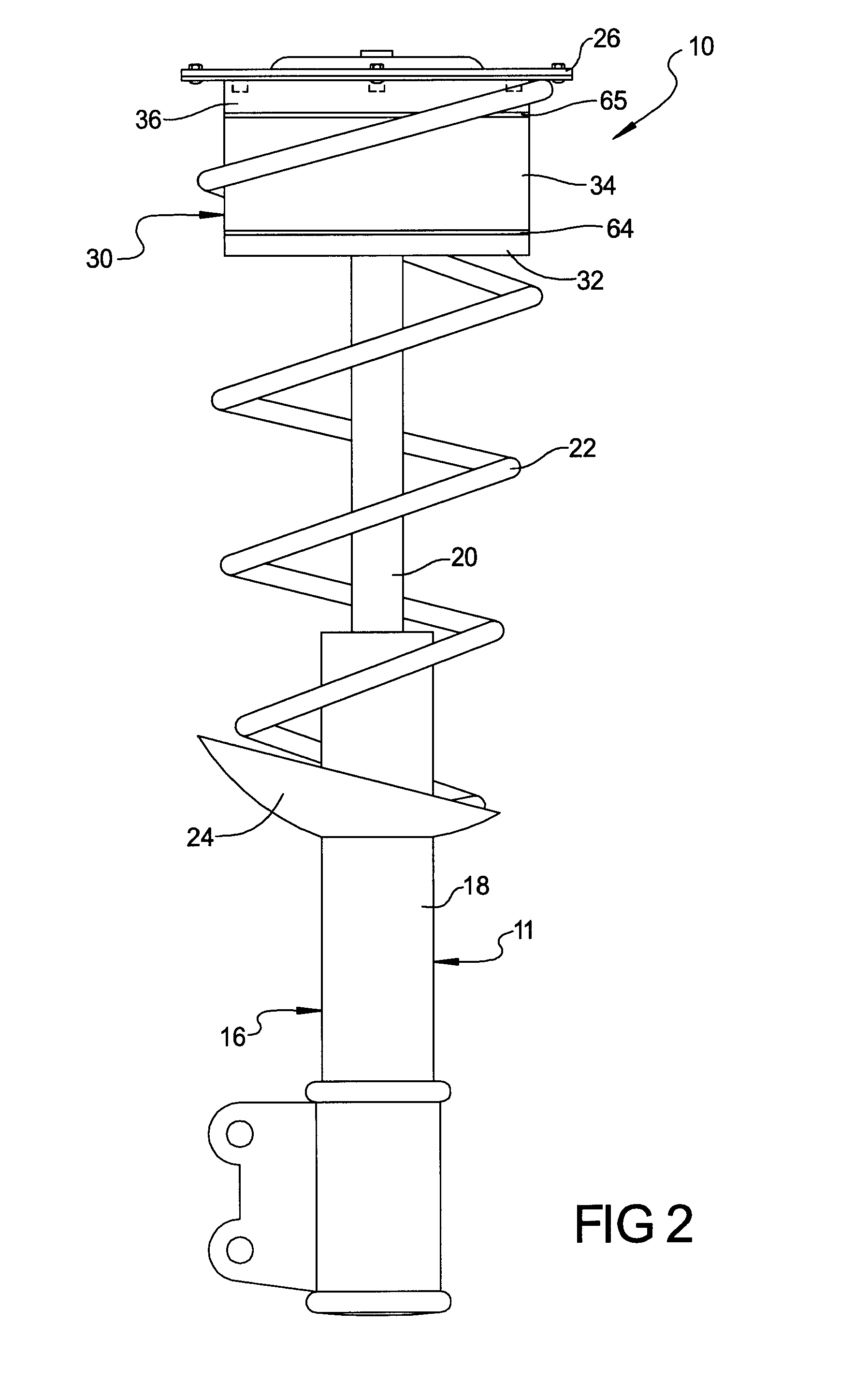
[0018]Referring to the drawings and in particular FIGS. 1 and 2, one embodiment of a damper assembly 10, according to the present invention, is shown for a suspension system, generally indicated at 11, of a vehicle 12 (partially shown). The vehicle 12 has a vehicle body 14 mounted on or integral with a vehicle chassis (not shown). It should be appreciated that the suspension system 11 is operatively connected between an unsprung portion, hereinafter referred to as unsprung mass and a sprung portion or vehicle chassis (not shown) of the vehicle 12.

[0019]The suspension system 11 includes a strut, generally indicated at 16, mounted between the unsprung mass (not shown) and the vehicle body 14 of the vehicle 12. The strut 16 includes a hydraulic cylinder 18 with an attached piston (not shown) and piston rod 20. The hydraulic cylinder 18 is attached to the vehicle chassis at its lower end by a suitable mechanism such as fasteners (not shown). The piston rod 20 slidably extends from the p...


PUM


Abstract

A damper assembly for a suspension system of a vehicle includes a housing adapted to be mounted to one end of a strut in the suspension system. The housing has a chamber with fluid therein. The damper assembly also includes at least one diaphragm extending across the chamber to react with the fluid, to be compliant at relatively small displacements, and to be rigid at relatively large displacements.

Description

TECHNICAL FIELD[0001]The present invention relates generally to suspension systems for vehicles and, more particularly, to a damper assembly for a suspension system of a vehicle.BACKGROUND OF THE INVENTION[0002]It is known to provide a suspension system for a vehicle such as a motor vehicle. One form of the suspension system includes a coil spring, one end of which rests in a lower seat moving with the wheel assembly; the opposite end contacts an upper seat of a vehicle body or frame of the vehicle. The spring supports the weight of the vehicle body and allows for reciprocating relative movement between the wheel assembly and the vehicle body during road travel to isolate wheel disturbances from the vehicle body.[0003]In another form of the suspension system, a strut is mounted between the movable suspension elements and the body of the vehicle. The strut typically includes a hydraulic cylinder with an attached piston and piston rod. The piston rod slidably extends from an upper end...

Claims


Application Information

Patent Timeline
Patent Type & Authority Applications(United States)
IPC IPC(8): F16F9/50
CPCB60G15/04B60G2200/142F16F9/54F16F9/48B60G2204/1242
Inventor OBLIZAJEK, KENNETH L.QUINN, SHAWN G.GREGORY, WILLIAM C.WRIGHT, CARL T.FADLER, GREGORY J.
Owner GM GLOBAL TECH OPERATIONS LLC
Why Eureka
Try Eureka