Motor control device

Active Publication Date: 2008-04-03
III HLDG 12 LLC
View PDF6 Cites 85 Cited by
  • Summary
  • Abstract
  • Description
  • Claims
  • Application Information

AI Technical Summary

Benefits of technology

[0023]In addition, a motor driving system according to the present invention includes a motor, an inverter that drives

Problems solved by technology

Although two current sensors (current transformers or the like) are usually used for detecting current values of two phases, the use of two current sensors causes an increase of cost of the entire system equipped with the motor.
In a

Method used


Image

  • Motor control device
  • Motor control device
  • Motor control device

Examples


first example

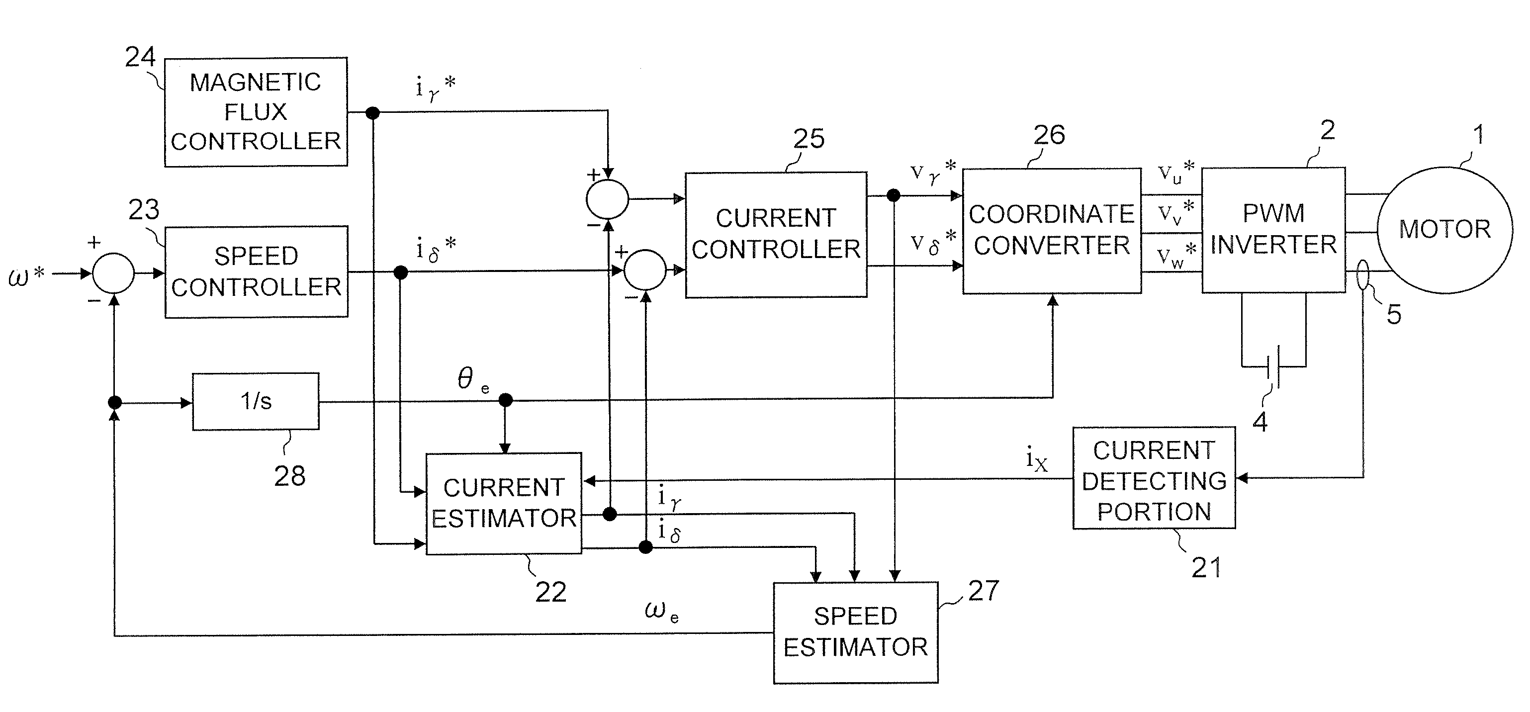
[0056]In the first place, a first example will be described. FIG. 3 is a block diagram of a general structure of a motor driving system according to the first example. In FIG. 3, the same parts as those shown in FIG. 1 are denoted by the same references.

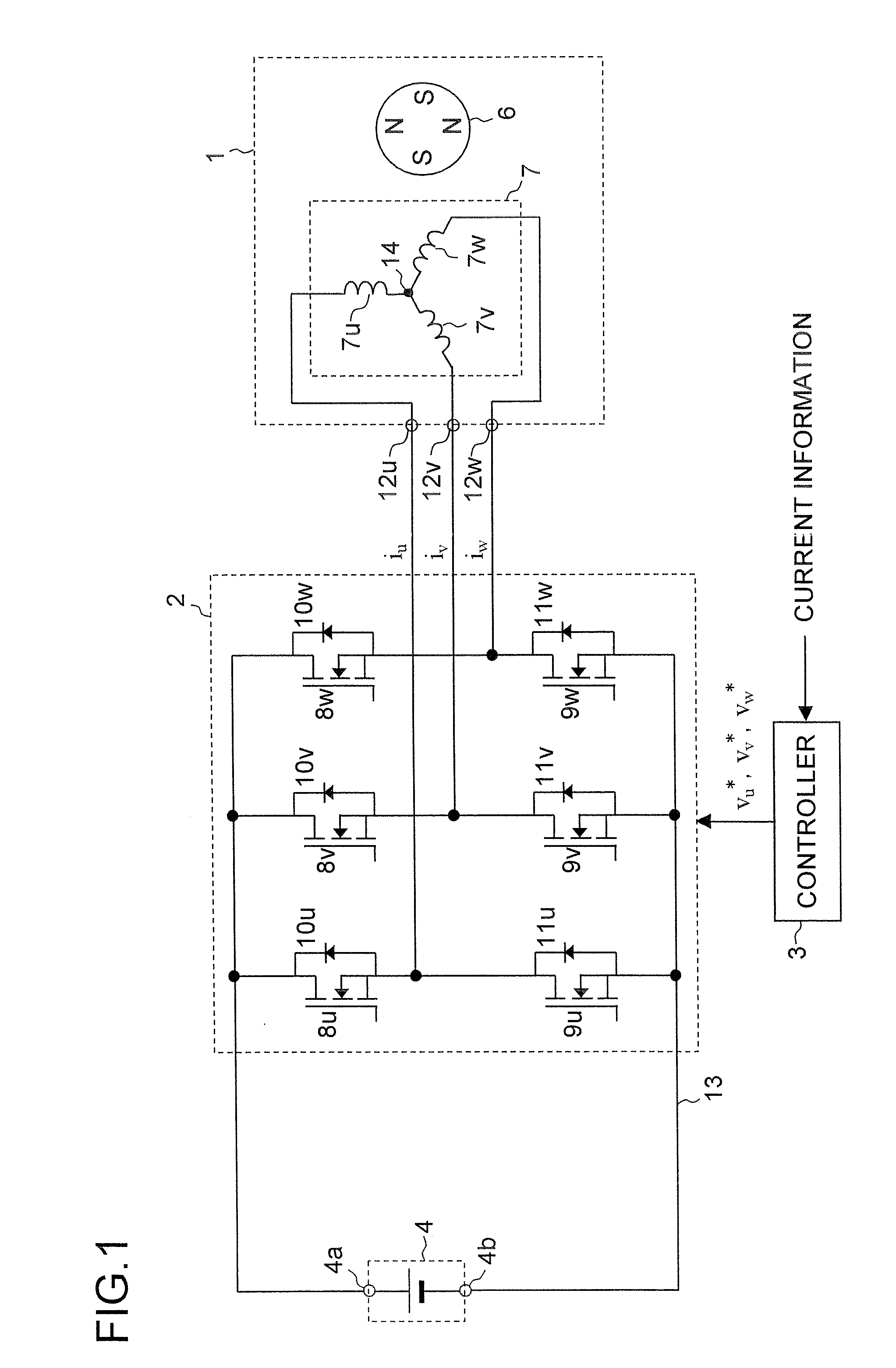
[0057]The motor driving system shown in FIG. 3 includes a motor 1, an inverter 2, a DC power supply 4 and a current sensor (current sensing element) 5. It also includes “a current detecting portion 21, a current estimator 22, a speed controller 23, a magnetic flux controller 24, a current controller 25, a coordinate converter 26, a speed estimator 27 and an integrator 28” that constitute the controller 3 shown in FIG. 1.

[0058]The current sensor 5 is disposed between the inverter 2 and the motor 1, and it senses phase current of one phase among three phase current (iu, iv and iw) flowing between the inverter 2 and the motor 1. In other words, the current sensor 5 senses one of the three phase currents iu, iv and iw (see FIG. 1). The c...

second example

[0073]Next, a second example will be described. FIG. 5 is a block diagram of a general structure of a motor driving system according to the second example. In FIG. 5, the same parts as in FIGS. 1 and 3 are denoted by the same references.

[0074]The motor driving system shown in FIG. 5 includes a motor 1, an inverter 2, a DC power supply 4 and a current sensor (current sensing element) 5a. It also includes “a current detecting portion 21a, a current estimator 22, a speed controller 23, a magnetic flux controller 24, a current controller 25, a coordinate converter 26, a speed estimator 27 and an integrator 28” that constitute the controller 3 shown in FIG. 1.

[0075]The motor driving system shown in FIG. 5 is different from the motor driving system shown in FIG. 3 in that the current sensor 5 and the current detecting portion 21 of the motor driving system shown in FIG. 3 are replaced with the current sensor 5a and the current detecting portion 21a, and the motor driving systems are the s...

third example

[0115]Next, a third example will be described. A general structural block diagram of the motor driving system according to the third example is the same as that shown in FIG. 5, so overlapping illustration will be omitted. However, in contrast to the second example in which the three-phase modulation is performed, the two-phase modulation is performed in the third example.

[0116]In a relationship with the three-phase modulation, the two-phase modulation will be described. First, the phase voltages when the three-phase modulation is performed are expressed by the equations (3a), (3b) and (3c) as below. Here, vu1, vv1 and vw1 respectively denote the U-phase voltage, the V-phase voltage and the W-phase voltage in the case where the three-phase modulation is performed, which are respectively equal to vu*, vv* and vw* in the case where the three-phase modulation is performed. In addition, “E” indicates a level of the DC voltage delivered by the DC power supply 4. “M” is a variable that de...


PUM


Abstract

A motor control device includes a current detecting portion that detects phase current of one phase among three phase currents supplied from an inverter to a motor, and a current estimator that estimates phase current of phases other than the detected phase current by using a specified current value indicating current to be supplied to the motor, and derives control current corresponding to the specified current value from the estimated phase current and the phase current of one phase. The motor control device controls the motor via the inverter so that the control current follows the specified current value.

Description

[0001]This nonprovisional application claims priority under 35 U.S.C. §119(a) on Patent Application No. 2006-264181 filed in Japan on Sep. 28, 2006, the entire contents of which are hereby incorporated by reference.BACKGROUND OF THE INVENTION[0002]1. Field of the Invention[0003]The present invention relates to a motor control device that drives and controls a motor.[0004]2. Description of Related Art[0005]In order to perform a vector control of a motor by supplying three-phase AC power to the motor, it is necessary to detect current values of two phases (e.g., U-phase current and V-phase current) among three phases including U-phase, V-phase and W-phase. Although two current sensors (current transformers or the like) are usually used for detecting current values of two phases, the use of two current sensors causes an increase of cost of the entire system equipped with the motor.[0006]For this reason, there is provided a conventional method in which bus current (DC current) between a...

Claims


Application Information

Patent Timeline
IPC IPC(8): H02P21/14H02P6/18H02P6/06H02P6/08H02P6/182H02P6/28
CPCH02P21/146H02M2001/0009H02M7/5395H02P21/18H02M1/0009
Inventor HASHIMOTO, EIICHIROHIDA, HAJIME
Owner III HLDG 12 LLC
Why Eureka
Try Eureka